OBDSTAR ECU Master Software Download, Register and Update Guide

1. Download Software
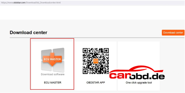
Visit OBDSTAR.com offcial site, go to Download Center. Download ECU Master PC software.
Operating System: Windows 10 or above
Language: English,Chinese
2. User Registration
Procedure:
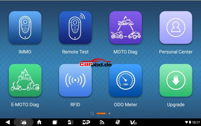
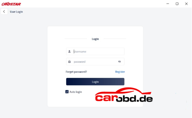
Clicking the “Personal Center ”icon displays the login screen.
Click” Register” button in the lower right corner and proceed the user registration interface.
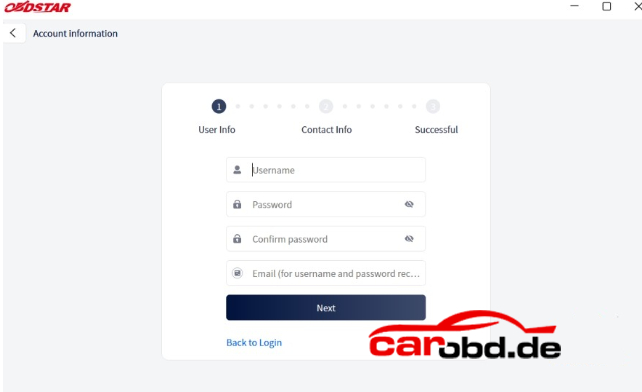
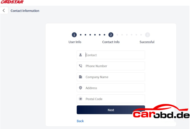
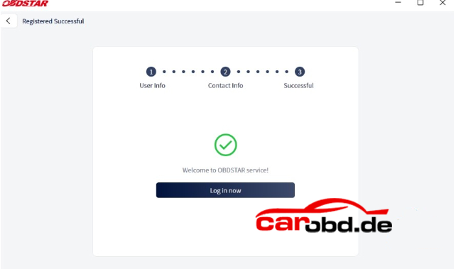
Fill in the required registration information. Once completed, you’ll see a success message. Click”Login Now” to continue
3. User Login
If you are already registered, enter your account and password, then click”Login”
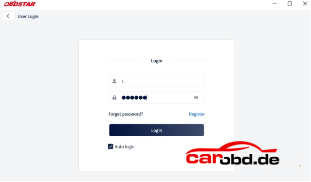
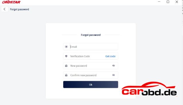
If you forget your password, click”Forget Password” on the login screen to go to the password recovery page. Enter the required information to reset your password.
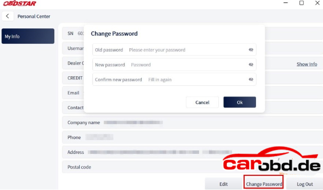
After Login , the user’s basic information is displayed and contact details or password can be updated.
Click”Edit” at the bottom of “My Info” screen to update your personal contact details.
Click” Change Password” at the bottom of “My Info” screen to modify your password.
4.Software Update
Users can download the basic data required for diagnosis, vehicle diagnostic software, data
package, etc. in this function module.
Follow the steps below to use it.
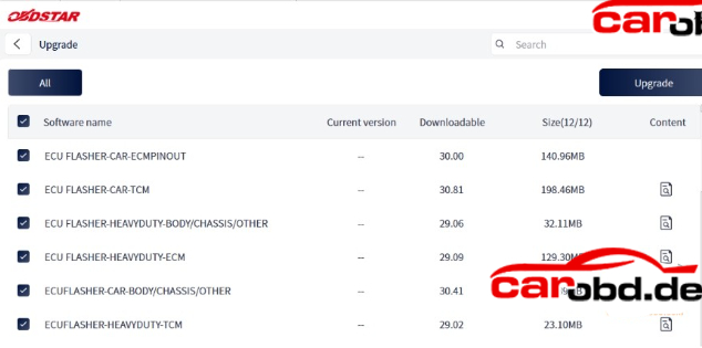
1) Log in to your account before using the Upgrade feature. After logging in, go to the Upgrade main screen, where all available updates are displayed.
By default, all upgradable software items are selected. To deselect an optional item, click the box next to the software name. Grayed-out checkboxes indicate mandatory software that must be upgraded and cannot be deselected. After selecting the software to upgrade, click the upgrade
button in the upper-right corner to begin the upgrade process. When the list contains many items, use the search bar in the upper-right corner to quickly find specific software by entering keywords or letters.
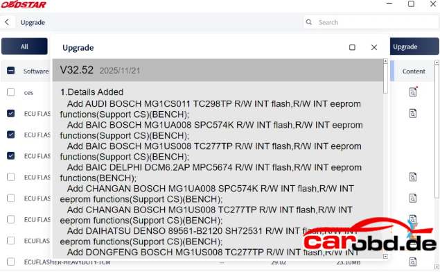
2) On the Upgrade main screen, the last column displays the upgrade content for each
software item. Click the icon button corresponding to a specific software entry to view
details about its version update
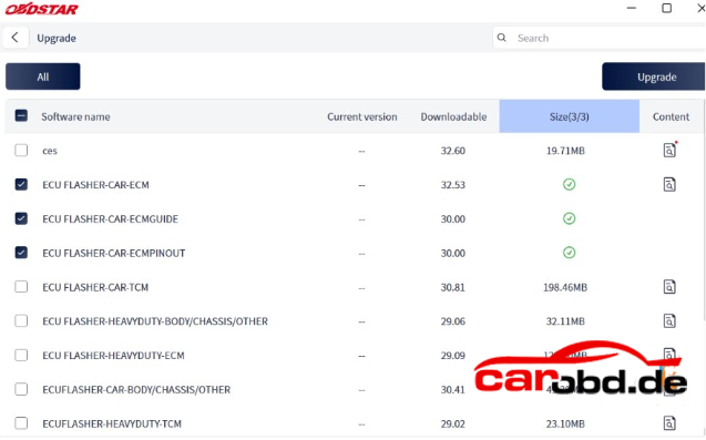
3) If you click the Upgrade button in the upper-right corner again while an upgrade is in
progress, a pop-up message will appear: “Downloading. Please try again after the download finishes.” Once a software item has finished downloading, a checkmark icon will appear in column 5 of that row to indicate completion
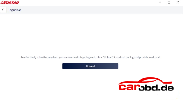
5. Log Upload
After clicking the [Log Upload] on the Support main page, the user can see the screen shown
in the figure below. Click [Upload] to upload your log.