Archive | January 2016

SPX AUTOBOSS OTC D730 Automotive Diagnostic Scanner with Built In Printer

spx-autoboss-otc-d730-automotive-diagnostic-scanner-blog-1

spx-autoboss-otc-d730-automotive-diagnostic-scanner-blog-3

spx-autoboss-otc-d730-automotive-diagnostic-scanner-blog-4


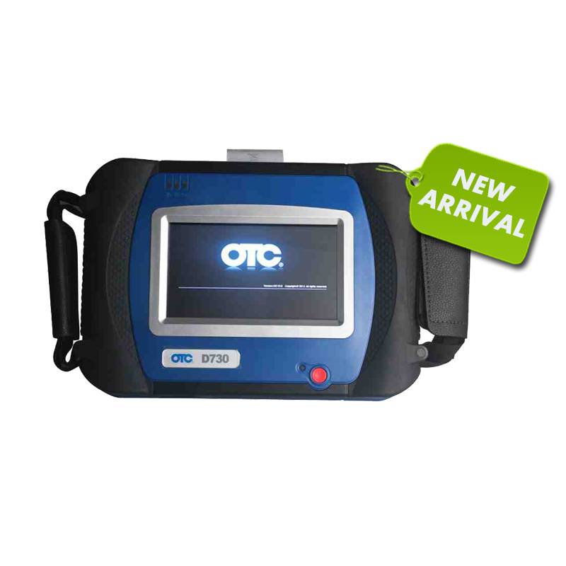
SPX AUTOBOSS OTC D730 highlight:

Multi-language available: English, Italian, German, French, Spanish, Russian, Polish and Turkish. Note: the default language is English; you are optional to download the language you want.
2. Update: frequent Internet based software updates.
4. Access to powertrain, chassis and body systems, it is new and powerful scan tool for workshop and car owner’s.
5. Covers more than 50 vehicle makes from Europe, America, Australia and Asia.
6. One Year Warranty
Built in Printer
High resolution 7” VGA colour TFT touchscreen display
Stand allowing hanging on steering wheel
Operation System (OS):

Windows CE operating system

SPX AUTOBOSS OTC D730 Automotive Diagnostic Scanner more details:

Following Content include:

1) SPX AUTOBOSS OTC D730 packages

2) OTC D730 Included Accessories

3) OTC D730 Vehicle Cable Complete Set

4) OTC D730 Scanner function

5) OTC D730 Scanner works with what electronic control system

6) OTC D730 works with what car models

Details:

SPX AUTOBOSS OTC D730 packages:

Being an automotive diagnostic scanner for all makes, it has a big package with all kinds of adapters and cables, its package weights 12.3KG (27.12LB )

Package including:

ASSM D730 EMEA

SD Card 8GB

Label of Microsoft WinCE

Benz-38 Adaptor

Chrysler-16 Adaptor CCD

Toyota-22 Connestor

Mitsubishi 12+16 Connestor

Honda-3 Connestor

Audi-4 Connestor

Nissan-14 Connestor

Benz-4 Connestor

Citroen-16C Connestor

Benz-14 Connestor

OBDll-16 Connestor

BMW-20 Connestor

Marelli-3 Connestor

GM/DEAWOO-12 Connestor

KIA-20 Connestor

Mazda-17 Connestor

TOYOTA-17 Connestor

Mini-3 Connestor

CITROEN-2 Connestor

Fiat-16 Connestor

Cigarette lighter line

Battery Cable

Main Cable 2M

Fuse 5A 30X6

Fuse 5A 20X6

PRINTING PAPER

SD Card Reader

D730 User Manual

AC/DC Adaptor

European Power Supply Plug

OTC D730 Included Accessories:

Carrying case

100 – 240 volt power supply

SD card reader

Built-in printer kit
OTC D730 Vehicle Cable Complete Set:

OBD II adapters

European OBD I adapters

Australian OBDI adapters

Asian OBD I adapters

USA Domestic OBD I adapters

Chinese adapters

We can FREE added new cars for you (if you need leave message on order)

OTC D730 Scanner function:

Quick Test function to test most vehicle systems
Fault codes (DTC’s), Data Stream and Service Reset
Actuations, Adaptations- and Control Module Coding
CAN Bus with high/low speed
One OBD II/EOBD connector for all CAN Bus systems
6 .Demo Mode for many OEM’s

Data graphing
Self-check function
OTC D730 Scanner works with what electronic control system?

Chassis :

SBC – Sensortronic Brake Control

ESP – Electronic Stability Program

AIRmatic – AIRmatic ABC

TPC – Tyre Pressure Monitor

ABS – SRS

Body:

Seats and Doors

Actual Values

Actuations

Initial Startup

Control Unit Adaptations

Correction Programming

Air Conditioning:

AAC – Automatic Air Conditioning

REAR AC – Rear Air Conditioning

STH – Stationary Heater

HSW – Heated Steering Wheel

Informatio n and Communication:

ICM – Instrument Cluster

SCM – Steering Column Module

PTS – Parktronic System

Audio, Video, Navigation

Telematics

Drive:

Transmission

ESM – Electronic Selector Module

DTR – Distronic

Motor Electronics

Idle Re-learn

Diesel Injector Coding

Diesel Pump Initialisation

DPF Regeneration

OTC D730 works with what car models?

European Vehicles : Audi, BMW, Citroen, Fiat, Ford, Jaguar, Lancia, Land Rover,Mini, Mercedes-Benz, Opel, Peugeot, Porsche, Renault, Seat,Skoda, Smart, Volkswagen and Volvo

American Vehicles: Chrysler, Ford and General Motors

Chinese Vehicles: Chery, Foton, Geely and Great Wall

Asian Vehicles: Daewoo, Honda, Hyundai, Infiniti, Isuzu, Kia, Lexus, Mazda,Mitsubishi, Nissan, SsangYong, Subaru, Suzuki and Toyota

AUSTRALIAN Vehicles: Ford and Holden

SD Connect C4 firmware update problems and solution

SD Connect C4 firmware update problems and solution

Question:

I have 5 Sdconnect multiplexers here.

They are all china clones.

Not all from same shop and not all same age(same SN).

I think the 2 which are still working might be the same.

tl;dr flashed multiplexers with toolkit, display doesn’t work anymore, power management pic chip bricked ?

In order to use them with the latest versions of star diagnosis

I needed to update the firmware.

The first 2 multiplexers updated just fine and also work with latest xentry.

But then i tried to update the 3rd one and 4th one.

bootimage and commandserver updated without an error, but then i flashed the power managment firmware. the display went dark and never came back. (the display went dark too when i flashed the first 2, but i came back after a second). the multiplexer is still booting and connecting to the pc. sd toolkit can still access the mux. xentry can still use it. however, xentry shows a voltage of 65 volts when the mux is only connected to 12v. Further diagnostics have not been testet. the toolkit shows all software versions as expected, except power managment is 0.0.0.

I can reflash power management, but without any result.

Is there a way to rescue or repair these 2 multiplexers?

Fix the power management chip somehow.

The fifth mux has some other damage, doesn’t boot. can be used for spare parts maybe.

How to properly update firmware?

You must update only 00, after the update open DAS Standalone, the rest of the updates automaticly install when you open DAS, don’t forget to install batterys!

MB SD Connect C4 firmware update procedure:

http://www.carobd.de/upload/pro/201601/mb-sd-c4-hardware-upgrade-instructions.rar

mb-sd-c4-star-diagnosis-1

Finally! Everything worked again

First of all, i am not talking about CSD 2.9, it is power management 2.8 and 2.9. i could update OS 2.3 and CSD 2.11 just fine.
all of these are included in the sdconnect toolkit.
only when i flahsed power management 2.9 (03_ PmPic29_cpld13), it bricked my power management chip.

i have multiple devices, i took them apart and changed the boards of the multiplexers. there was one board that was able to flash the power management and everything worked again.

Clone 4D transponder with Zed-BULL and TPX Cloner Module

Clone 4D transponder with Zed-BULL and TPX Cloner Module

1.Please connect TPX cloner Module to Zed-bull using cable and give power both to Zed-bull and TPX Cloner Module.

Cloning-4D-transponder-using-Zed-BULL-1

Cloning-4D-transponder-using-Zed-BULL-2

Cloning-4D-transponder-using-Zed-BULL-3

2.Please put original key to zedbull antenna, select “Copy” and press “Enter” and “R” Button.

Cloning-4D-transponder-using-Zed-BULL-4

Cloning-4D-transponder-using-Zed-BULL-5

3. Caution! Put the original key and press R! Don’t remove the key during the process!

Cloning-4D-transponder-using-Zed-BULL-6


4. Press “W” button and select TPX Cloner module.

Cloning-4D-transponder-using-Zed-BULL-7

Cloning-4D-transponder-using-Zed-BULL-8


5.Writing, connection and calculating, calculating may take up to 2 minutes.

Cloning-4D-transponder-using-Zed-BULL-9

6. Calculation Ok, please put TPX2 or EH2 to Zed-BULL antenna and press “W” button.

Cloning-4D-transponder-using-Zed-BULL-10

7. Verifying, and successful.

Cloning-4D-transponder-using-Zed-BULL-11

Bosch ESI Tronic Installation Step by Step

Here we start:
1: Mount ESI Tronic Iso image “Recommend Magicdisc”.
2: Open the bosch ESI DVD and then run Setup.exe.
3: Few sec’s then this window will appear, select your language -> Continue.

BOSCH-ESI-Setup-1

4: New window will appear, Select user defined installation and leave I-key blanked -> Continue.

BOSCH-ESI-Setup-2

5: Chose your Installation Directory -> Continue.

BOSCH-ESI-Setup-3

6: New window will appear, just tick what u want (4ex: screen saver or Fuel injection pump section…).

BOSCH-ESI-Setup-4

7: U will get this window.

BOSCH-ESI-Setup-5

8: Drag and Drop the bases you want to install.

BOSCH-ESI-Setup-6

9: New window will appear, click Continue.

BOSCH-ESI-Setup-7

10: Installation will Start

BOSCH-ESI-Setup-8

11: Take a cup of coffee till the installation is finished.
OBD2 enginner Note: During the installation it will ask you to import DVD 2 so just mount Image 2 and then Continue.
Now this window will appear, Click Close.

BOSCH-ESI-Setup-9

12: New window will appear, U can click Yes “If u want to enter the license now” OR Click No ” If u want to install the license after installation is finished.
In this case, I’ll click NO.

BOSCH-ESI-Setup-10

13: Restart windows by clicking finish.

BOSCH-ESI-Setup-11

14: Now here you see how to activate ur ESI.

BOSCH-ESI-Setup-12

15: New window will appear, Customer code could be any number, to get ur Release code, copy ID no. to keygen, generate, then paste the Release code back to the window.

BOSCH-ESI-Setup-13

16: after you paste your Activation key , then click Ok.

BOSCH-ESI-Setup-14

17: Click close. Job is done en the bosch ESI DVD and then run Setup.exe.

Engine Control Module Recovery by GM MDI or Tech 2

This is step-by-step instruction on how to do engine control module recovery on Cadillac cars.

modules tested successfully with the tools and guide below:
2009 Buick Enclave
2007-2009 Cadillac CTS, SRX, STS
2009 Chevrolet Traverse
2007 GMC Acadia
2009 GMC Acadia
2007 Saturn OUTLOOK
2009 Saturn OUTLOOK

Diagnostic tool:
GM MDI module/
GM GM Tech2 GM with 32MB Card and TIS2000

gm-tech2-gm-diagnostic-scanner-blog-1
Engine control module recovery procedure:
1. Disconnect the programming device.
2. Power down the control modules connected to the GMLAN bus by disconnecting the positive battery cable for 2 minutes.
3. Reconnect the positive battery cable.
4. Determine which programming device will be used to perform the recovery steps.
If using MDI, connect to the programming station or Notebook using a cable (LAN). Proceed to Step 5 and then Steps 6-8.
If using a Tech 2 proceed to Steps 6-8.
5. Reboot the programming station or Notebook. This is to make sure nothing is in memory.
Kindly Note: Selecting Replace and Reprogram from the Select Diagnostic Tool and Process Screen is REQUIRED because some of the calibrations may be erased from the initial attempt to reprogram the module.
6. Reprogram the engine control module. Select Replace and Reprogram from the Select Diagnostic Tooland Process Screen.
7. Follow the on-screen instructions to complete the programming event.
8. Clear all DTCs using the GM Tech2 GM with 32MB Card and TIS2000 or GDS.

(Solved) K+DCAN INPA Interface INITIALIZATION ERROR

My k+dcan interface shows error: INITIALIZATION ERROR. killed several hours with this knock-off and i’m about to destroy my laptop because of frustration.

Car: BMW 2011 – e92 – LCI.

i have set the COM to 1, obd.ini is alos COM1. i don’t get it.

ediabas-bmw-inpa-k-can-blog-1
SOLVED:
(solution offered by an experienced user with K+Dcan cable)

i had to modify the EDIBAS.INI

as follows

RemoteHost
; Description : server address/name
; Default = –
; RemoteHost = Desmo16

Desmo16 being my computer’s name (note that this must be maximum 8 chars)

and

Port
; Description : IP communication port
; Value : 1000 < port < 30000
;
; Spezialfall OP(P)S /ICOM:
; Value : 6801 ;OBD-Treiber (CAN)
; Value : 6802 ;Most-Treiber
;
; Default = –
; Port = 6801

OBD2 notice that you should be sure port is 6801 as mine was 3000.

i also ran the DCAN utility found here: http://osefactory.com/tools/k+dcan/

and set it on 500 kbit DCAN

it worked like a charm after i made these mods.