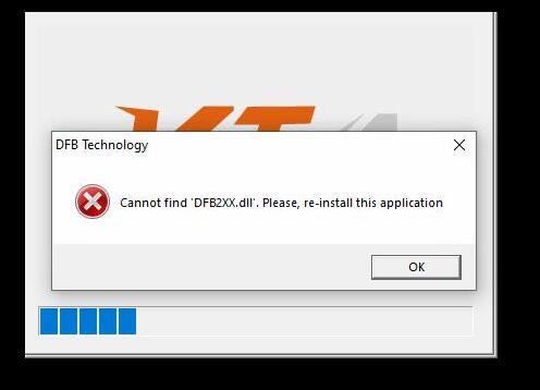
How to solve the problem when Fetrotech Tool software opens but flashes back and the taskbar disappears.
At present, it can only be solved by replacing the system, taking our windows 11 pro 64bit installation as an example:
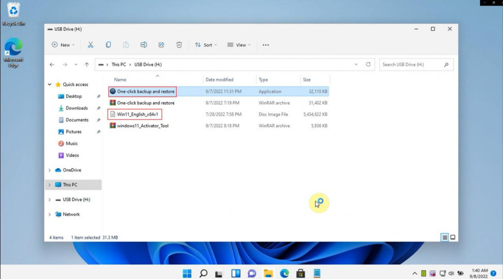
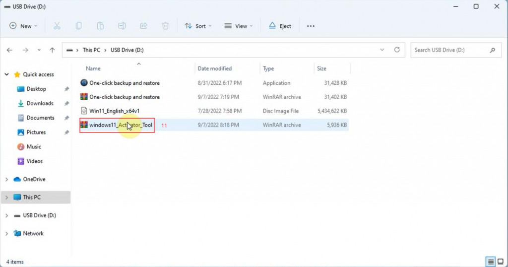
1. The customer can download the Windows 11 pro 64bit English system package, one-click backup and restore tool and system activation tool.
Windows 11 pro 64bit English system package download link:
https://mega.nz/file/rIBRELxS#6Maa1nV-oRfUsEns38jWbc_Pu3MQufd2ygvABxk65Wc
One-click backup and restore tool:
https://mega.nz/file/GUBQSYSI#cueWd9pgIi6U7Nk9f8deH9qHAr4umTOSFsZ7e5wt4fU
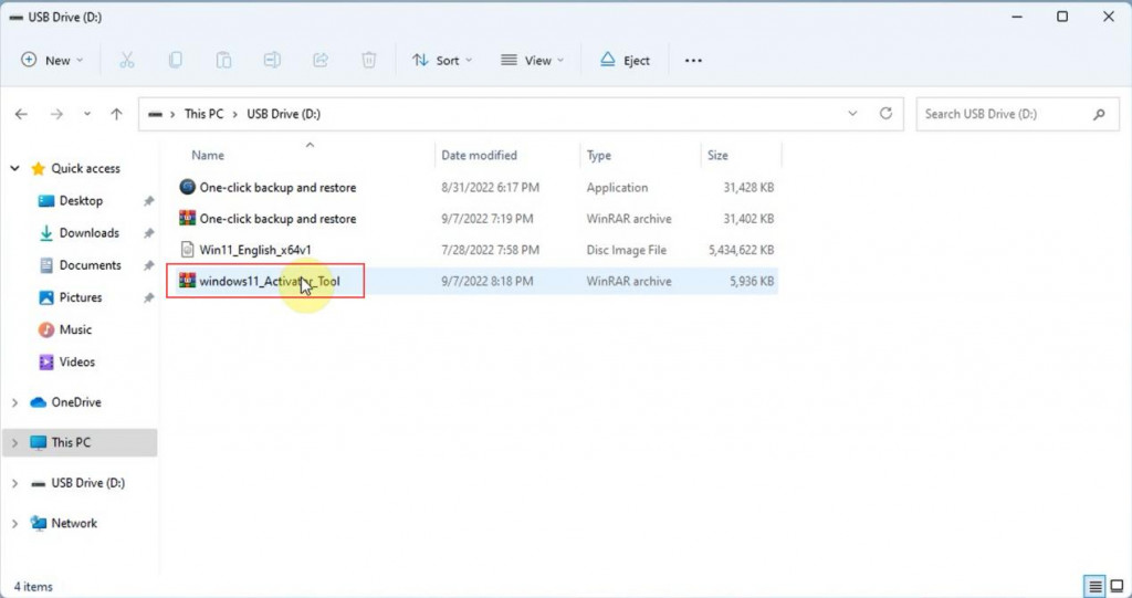
Windows 11 system activation tool:
https://mega.nz/file/OFYRxBDD#iPAFckU6B3efqBn6OxKueLIxbCfU08Q5cYjQCgsbzxs
Notice:
(1) Before reinstalling the system, you need to close the anti-virus software, otherwise the “One-click backup and restore tool” will not work.
(2) Before reinstalling the system, please back up important files on the C drive (the C drive will be formatted and deleted after the system is reinstalled)
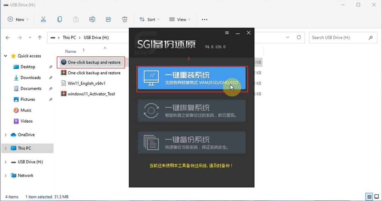
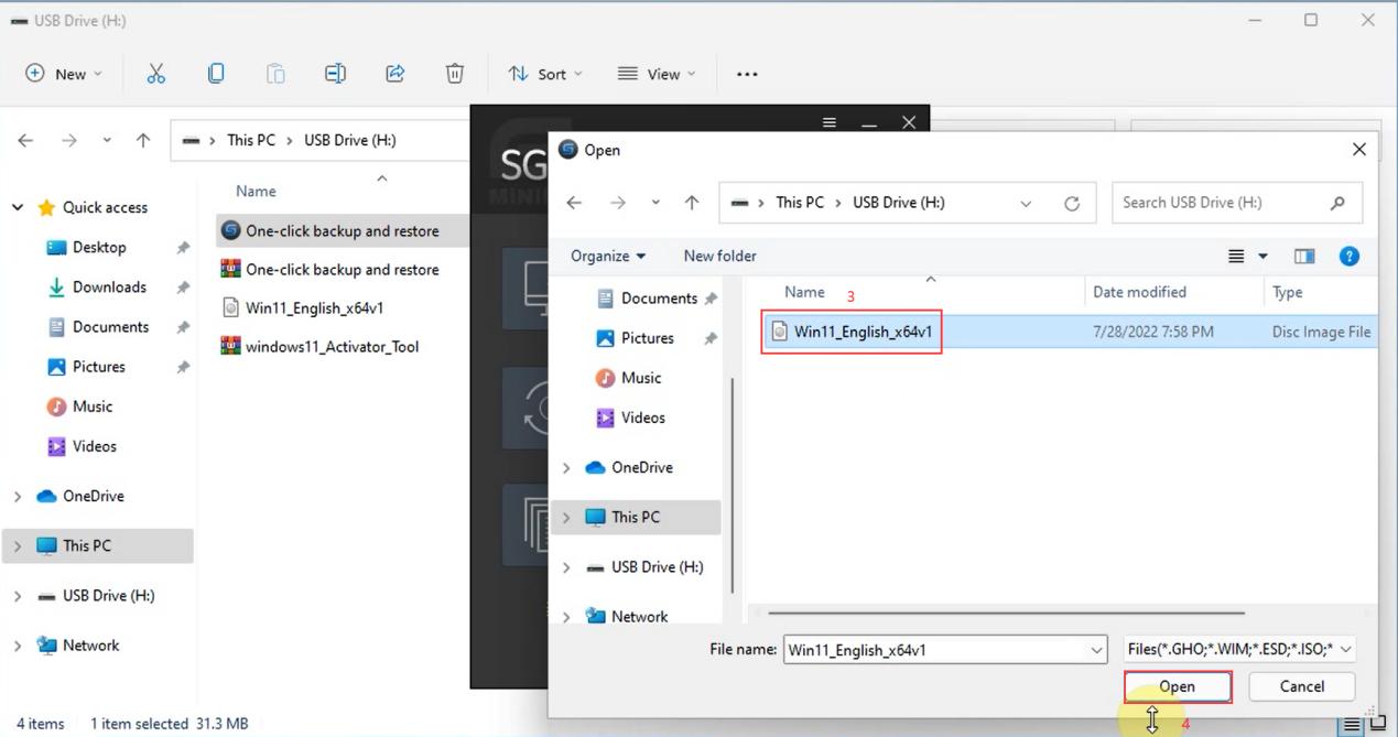
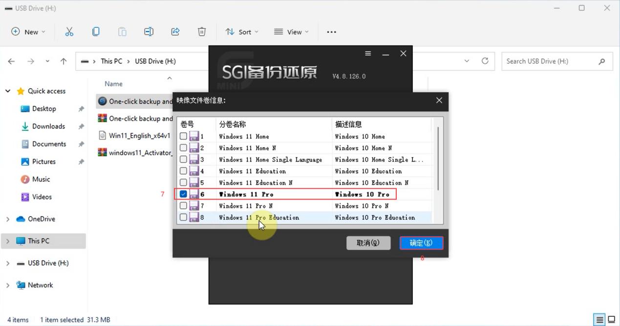
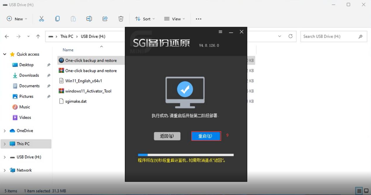
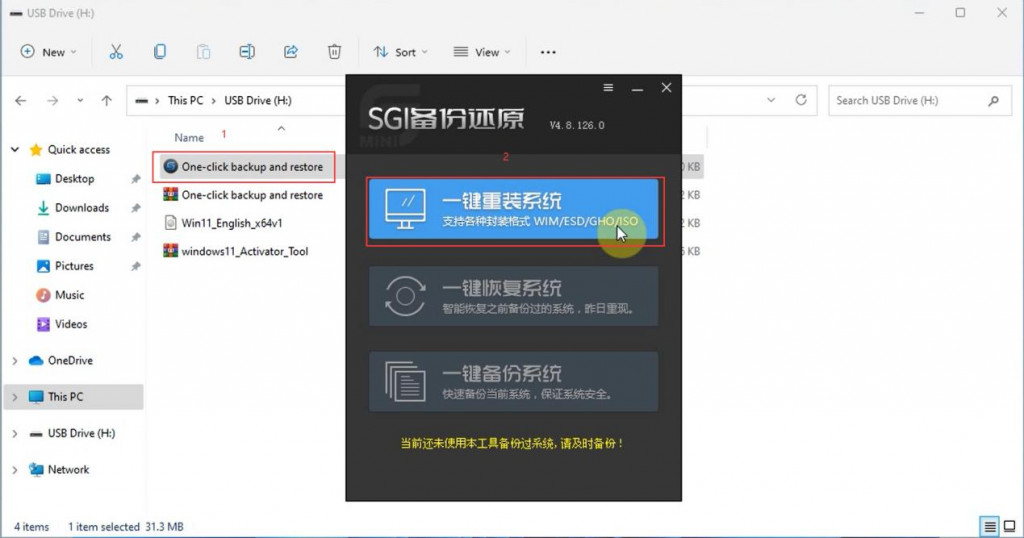
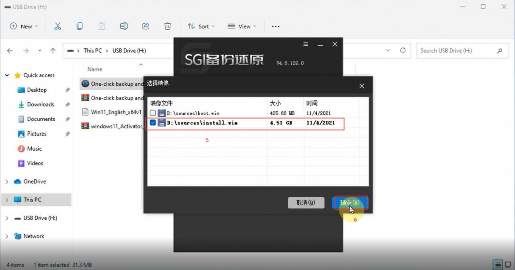
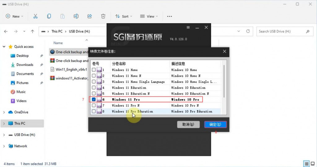
2. Open the “One-key backup and restore” tool, select the first “One-key reinstall system” menu, and then select the win11 64bit system package to open, as the following figure shows.

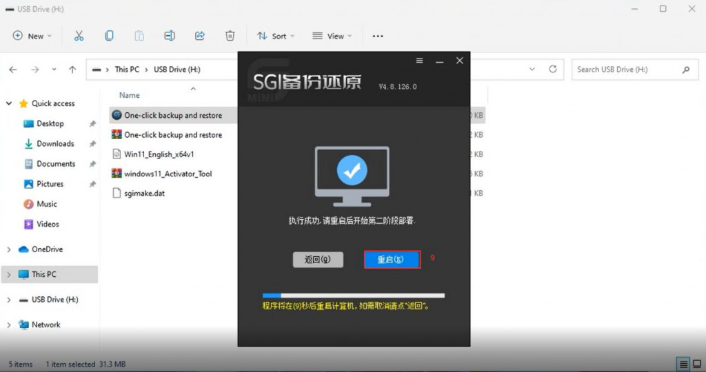
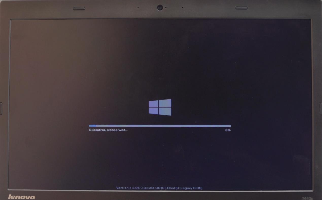
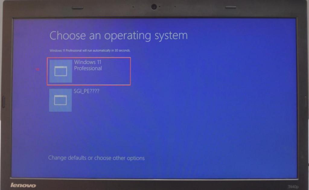
3. Restart the computer and decompress the system package, and then install the system automatically (Please plug in the computer, do not operate the computer during the installation process, please wait 10-25 minutes)

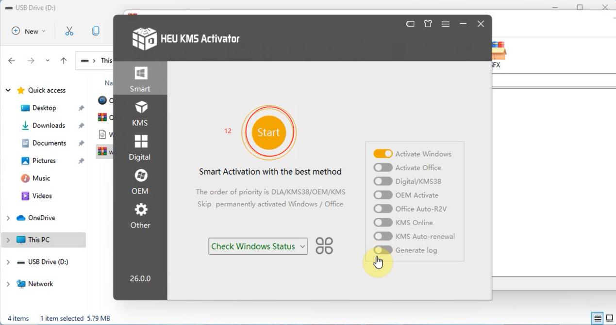
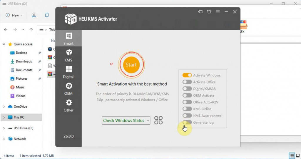
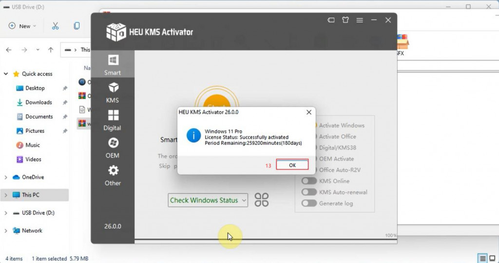
4. After the system is installed, activate the Windows 11 system
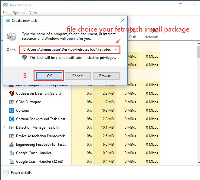
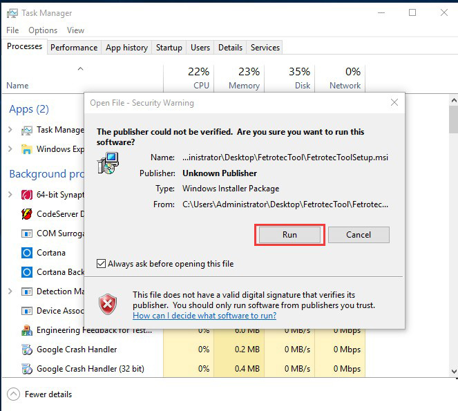
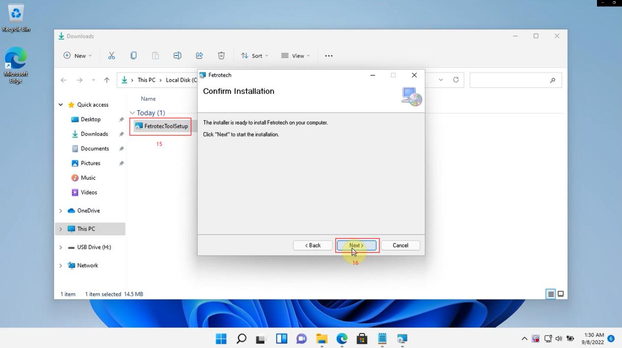
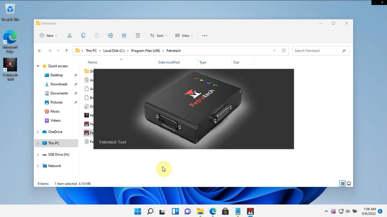
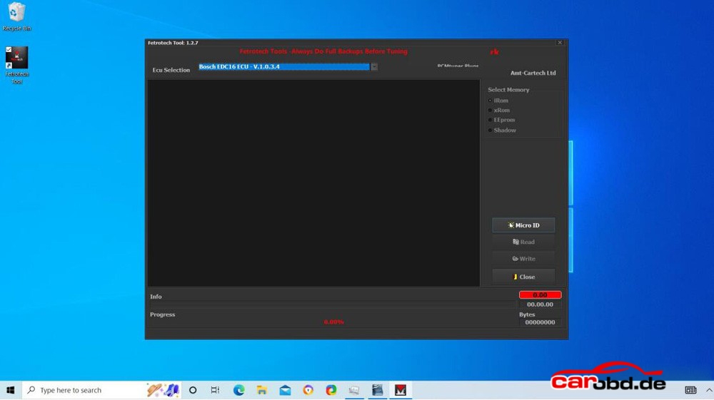
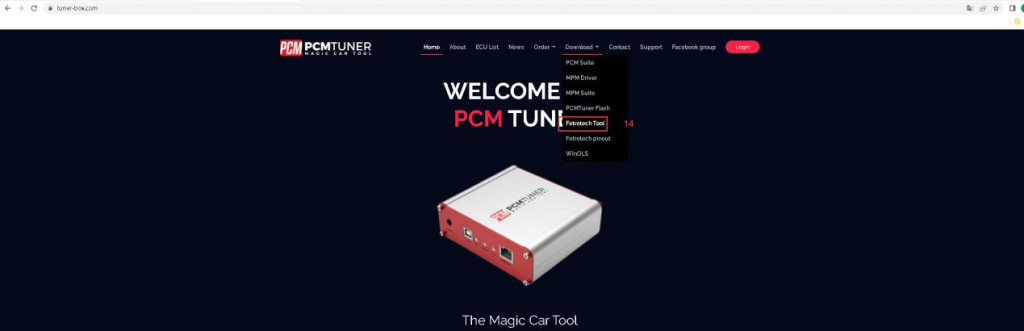
5. Go to the official website (www.tuner-box.com) to download the Fetrotech Tool software, and then run the installation.

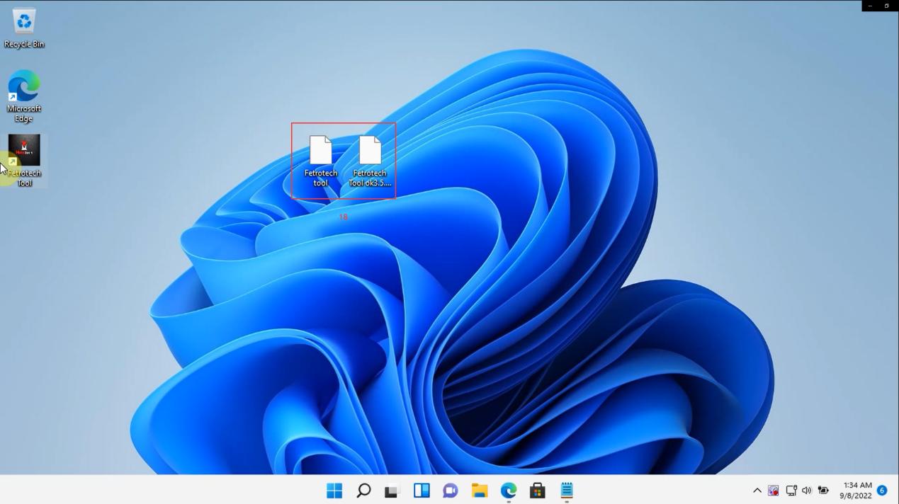
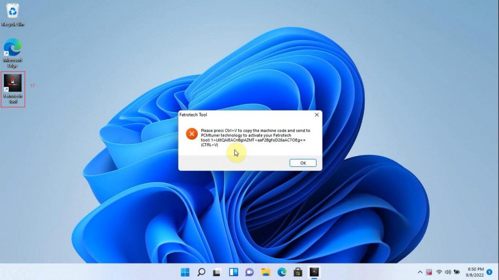
6. After installing the software, open it, copy the ID and serial number of the device according to the prompt, “Ctrl + V” and send it to the seller for activation
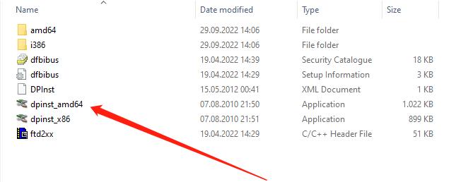
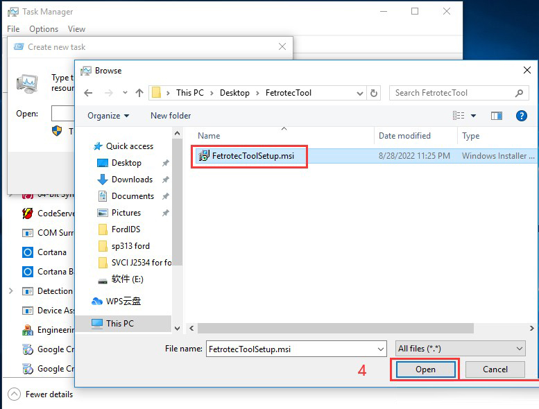
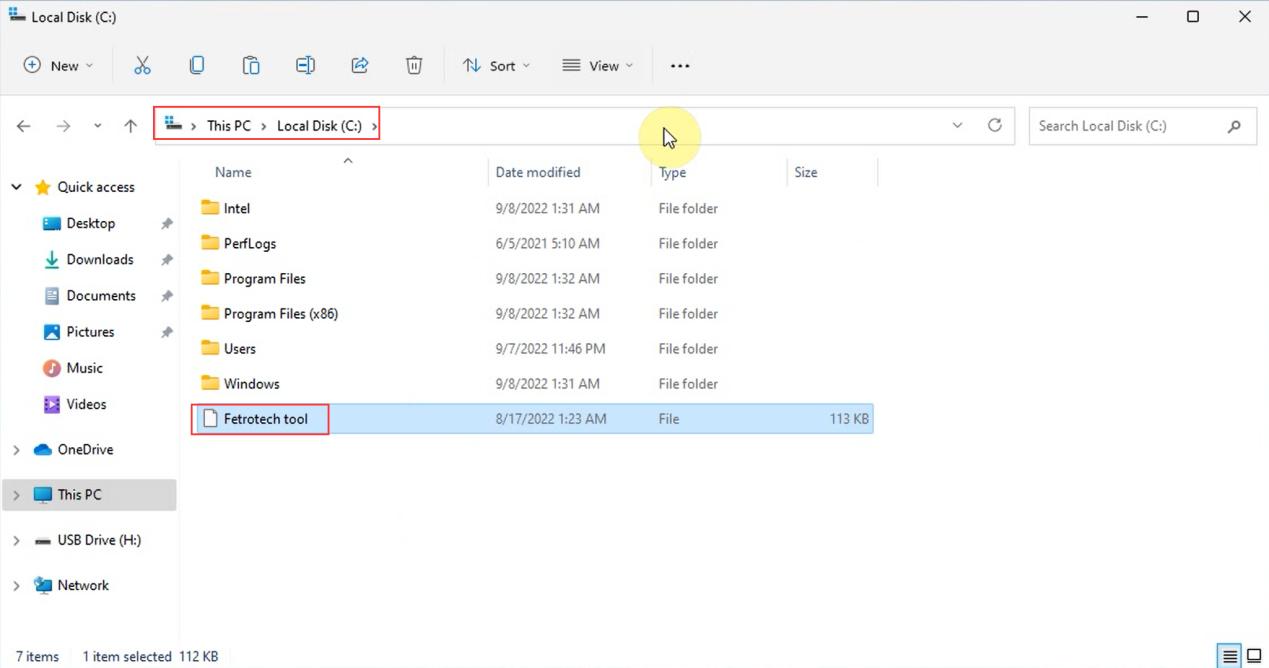
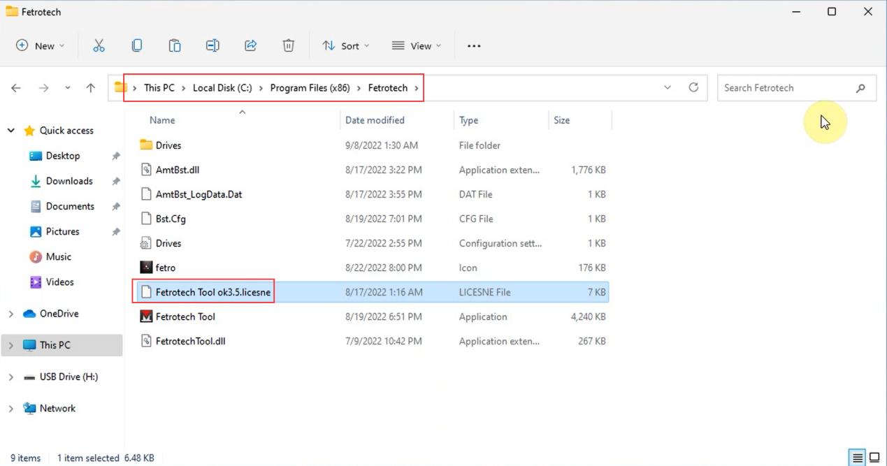
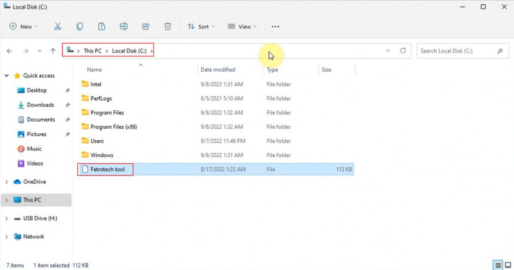
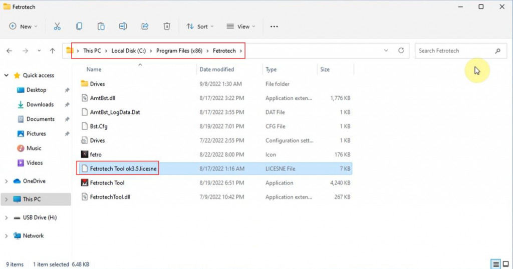
7. The seller returns the two activation files “Fetrotech tool” and “Fetrotech Tool ok3.5.licesne”, and then copy them to the corresponding directory, as the figure shows below:

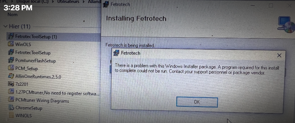
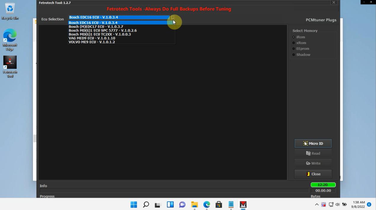
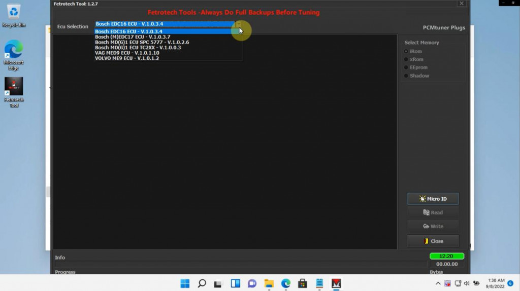
8. Connect the fetrotech device to open the software (if an error occurs, please reinstall the software)

for more informations,please check the youtube video, it will be more clearly to follow
https://youtu.be/Ouix-yf8GpE