Solution for PCMtuner flash No Found Problem

PCMtuner ecu scanner is not updated to V1.27, when opening the software and click”Read and Write”, it will show“PCMtuner Flash not Found”

QQ截图20220810144257

But how to solve this problem?Here we share steps to correct the problem.

1.Please download the PCMtuner Flash from official site”tuner-box.com” or from this download link and then install it.

QQ图片20220808173415

2.After finishing the installation, please open it and then please send the”Serial Number” on the back of device and the ID to”info@tuner-box.com”

factory will send license file back to you.

QQ图片20220808173426

QQ图片20220810145206

3.When customer get the license file from factory,please copy it to”PCMtuner Flash”file.

QQ图片20220808173444

for more steps,please check following videos

https://youtu.be/8p8TJM_VYnA


VOCOM II Mini Dongle WIFI Setting and Firmware Update Guide

VOCOMII dongle, produced by ACTIA in Germany, covers all the functions of the VOCOM2 VOCOMII 88890400, which doesn’t need any cables accessories because it can be connected to the laptop via WIFI perfectly. It is a portable vehicle communication device for its size and weight.

Here we share the steps for wifi setting and firmware update guide

First of all, WIFI Settings

1.Power on the vocom2 dongle and the lights will be flashing. Find the WIFI signal Vocom2D_******* from the laptop. Click connect.
VOCOM2 Dongle WIFI Setting 1VOCOM2 Dongle WIFI Setting 2
2.Input “v2d+ SN num”, SN number is 7 digits which you can find it from the back of the VOCOM2 dongle. Then click OK. And done.

VOCOM2 Dongle WIFI Setting 3VOCOM2 Dongle WIFI Setting 4

Second, Firmware update guide:
Pls be sure that the vocom2 dongle be power up by 24V ECU or truck. Low voltage will be affect the firmware update.
1.After the WIFI setting well, go to All Programs and then VOCOMII.
firmware update 1
Click the VOCOMII Configurator.
firmware update 2
You will see the windows as below. And Click the place as the pictures bellowed.
firmware update 3
Then choose “ Advanced” Update Device Firmware
firmware update 4
You will see the windows as below. And Click the place as the pictures bellowed. And wait until it is finished.
firmware update 5

firmware update 6

firmware update 7

firmware update 8

firmware update 9

firmware update 10

It will run the TECH TOOL automatically when firmware update finished.
firmware update 11

firmware update 12

It is done now.

firmware update 13

OBDSTAR X300 DP Plus Calculate YAMAHA MOTORCYCLE PROXIMITY 6-DIGIT PINCODE by Using Motorcycle IMMO Configuration 1

OBDSTAR X300 DP Plus Calculate YAMAHA MOTORCYCLE PROXIMITY 6-DIGIT PINCODE by Using Motorcycle IMMO Configuration 1

SP326 SF297 Calculate YAMAHA MOTORCYCLE PROXIMITY 6-DIGIT PINCODE

Step1: please connect X300 DP Plus via main cable and also prepare P001 programmer and proximity key.

Besides, please keep Key Master DP Plus in charging and comunication in the whole process.

obdstar x300 dp plus calculate yamaha pin code_1

Step2:Select”Car IMMO”-“Pin Code”Newest Version-“Yamaha Motorcycle”-“NMAX”

obdstar x300 dp plus calculate yamaha pin code_4

obdstar x300 dp plus calculate yamaha pin code_5

obdstar x300 dp plus calculate yamaha pin code_6   obdstar x300 dp plus calculate yamaha pin code_7 obdstar x300 dp plus calculate yamaha pin code_8

Step3: There are 3 kind of method to tell how to get the pin code

Here is the Method 1: P001 read key ID to calculate 6-digit PIN

obdstar x300 dp plus calculate yamaha pin code_9

Connect P001 programmer with main cable

obdstar x300 dp plus calculate yamaha pin code_10

Enter the programm

obdstar x300 dp plus calculate yamaha pin code_11

Please note checking pincode requires 8 credits each time,click”OK”

obdstar x300 dp plus calculate yamaha pin code_18

Put original proximity key into P001 programmer,click”Enter”

obdstar x300 dp plus calculate yamaha pin code_13

Confirm 8 credits

obdstar x300 dp plus calculate yamaha pin code_14

PinCode had been read out successfully

obdstar x300 dp plus calculate yamaha pin code_15

Method2: Enter key ID to calculate 6-digit PIN

obdstar x300 dp plus calculate yamaha pin code_16

Enter key ID to calculate 6-digit PIN-“Enter”

obdstar x300 dp plus calculate yamaha pin code_17

Pls note checking pincode requires 8 credits each time,Click”Ok”

obdstar x300 dp plus calculate yamaha pin code_12

Please enter the 8-digit key ID,click”Enter”(key ID inside the proximity key)

obdstar x300 dp plus calculate yamaha pin code_19

PinCode has been calculated out successfully

obdstar x300 dp plus calculate yamaha pin code_20

Method3: Load eeprom to calculate 6-digit PIN(except for YAMAHA TMAX)

obdstar x300 dp plus calculate yamaha pin code_21

Load EEPROM to calculate 6-digit PIN-“Enter”

obdstar x300 dp plus calculate yamaha pin code_22

Checking pincode requires 8 credits each time, click”OK”


obdstar x300 dp plus calculate yamaha pin code_23

Load EEPROM of YAMAHA motorcycle,click”Enter”

obdstar x300 dp plus calculate yamaha pin code_24

Confirm 8 credits

obdstar x300 dp plus calculate yamaha pin code_25

PinCode has been calculated out successfully

obdstar x300 dp plus calculate yamaha pin code_26

Then add a key or do all keys lost via pin code

obdstar x300 dp plus calculate yamaha pin code_2

PCMTuner Module 71 Bench Mode Not Working Solution

PCMTuner Module 71 Bench Mode Not Working Solution


Here are the tips if failed to read ecu edc17cp45, edc17c06 etc on bench mode with pcmtuner module 71.

PCMTuner comes with spare transistors for GPT circuits, lots of people damage these by connecting wrongly to ECU so these are replacements if it happens.

PCMTuner EDC17CP45 EDC17C06 etc Bench Mode Not Working 1

If you use OBD for power supply, please do not plug in a separate 12V, otherwise, it will cause the device transistor or step-down chip to burn.

MUST USE PCMtuner power supply!
If you use your own lab power and voltage regulator. You don’t know how device power works. Just adjust the voltage to 13.5 or whatever you think will cause the whole triode to burn out.

The solution here helps many users with similar problems. edc17c60, edc17cp45, edc17cp06 all tested working on bench mode.
Resoldered two transistors K1P, and work bench mode. One soldered K1P other analog p1P, I had only one K1P.
PCMTuner EDC17CP45 EDC17C06 etc Bench Mode Not Working 2
PCMTuner EDC17CP45 EDC17C06 etc Bench Mode Not Working 3

replace first this transistor, K1P, analog 1P,p1P

k1p mmbt2222a – 0.6A 40/75V and p1p pmbt2222a – 0.8A 40/75V

PCMTuner EDC17CP45 EDC17C06 etc Bench Mode Not Working 4

PCMTuner EDC17CP45 EDC17C06 etc Bench Mode Not Working 5

PCMTuner EDC17CP45 EDC17C06 etc Bench Mode Not Working 6
Read on bench module 71 successfully.

PCMTuner EDC17CP45 EDC17C06 etc Bench Mode Not Working 7
If not working after replacing these resistors, check other transistor positions and get it replaced.

PCMTuner Facorty Solution:
PCMTuner EDC17CP45 EDC17C06 etc Bench Mode Not Working 8

N1 transistor: MMUN2113LT1G
N2, N3 transistor: MMUN2211LT1G
Q3 Q9 Q10 Q11: MMBT222A-7-F
The corresponding positions are marked below:
PCMTuner EDC17CP45 EDC17C06 etc Bench Mode Not Working 9

Q3, Q9, Q10, Q11 transistor: with MMBT2222A-7-F
The corresponding positions are marked below:
PCMTuner EDC17CP45 EDC17C06 etc Bench Mode Not Working 10

Free Green Chiptuning Tokens for PCMtuner New Users

Free Green Chiptuning Tokens for PCMtuner New Users

PCMtuner company now released a new promotion for new users.

Buy “PCMtuner” and get Green Chiptuning Tokens from “VZ-Performance Center”

Promotion: Customers who purchase PCMtuner products (complete set of PCMtuner machine or a single PCMtuner dongle) can get 3 green tokens for free (The total value is €270.00, which can be seen from the VZ-Performance official website), from June 28th to July 20th.

get free token

But how to get the 3 Free Green Tokens?

For customers who purchased pcmtuner products during the promotion.

a. After receiving the device, please complete the registration process.

b. After finish the registration, please log into VZ performance official website (https://support.vz-performance.com).

c. Create a “general support” ticket to request recharge as shown in the picture below.

get free token 1

VZ-Performance Green Chiptuning Tokens Can be Used for the Services Below:

GPF/OPF Removal

EGR Removal

DTC Removal

ADBlue Removal

HOT Start Fix

IMMO Removal

Readiness Calibration

Flaps / Swirl Removal

TVA Removal

Sport Displays Calibration

Cold Start Noise Reduction

Kickdown Deactivation

StartStop Disable
MAF Removal

Speed Limiter Removal

Torque Monitoring Disable

Burbles Activation

Popcorn Activation

EVAP Removal

Exhaust Flap Removal

SAP Removal

AGS Removal

BMS/BPCM

Lambda/O2 Removal

Launch Control

OBD Reading Protection

Boost Sensor Calibration

LC, AL and NLS for MED9.1

Checksum Fix

Stage1

Stage2

Stage3


Tips to Read Honda CIVIC 1800 MED17.9.3 ECU by PCMTuner

Tips to Read Honda CIVIC 1800 MED17.9.3 ECU by PCMTuner

PCMTUNER ECU Programmer Honda CIVIC 1800 I-VTEC 141HP 2012-2018 MED17.9.3 ECU Reading On Bench Tips:
1-2

Steps:

Use a universal cable connect the ECU to PCMtuner BENCH/BOOT port
USB cable connect laptop and PCMtuner
Power adapater connect PCMtuner for ensure power supply
You can read and write the ECU

Notice: dont forget make fullbackup before you do any work,that will always make your work safe Fullbackup mean read eeprom and flash then save it.

Please select the 71 protocols TC1793 for read flash and eeprom when you connect all cable and back to click start read and write(software will forward to read and write GUI).
Attention: all user better read fullbackup( read flash and eeprom) for keep safe.

Pinout Instruction:

3-3


How to Stop PCMTuner PCMFlash Updates?

How to Stop PCMTuner PCMFlash Updates?

Do remember always update pcmtuner software. Never update pcm-flash software online.

This is the message we want to get rid of.

“PCM-FLASH: An updated version was found on the server, would you like to download build 1.2.5 released on 2022-02-20”
22061416552599519282副本

Firewall needs to be active.

22061416552599536841副本

First, get into the windows settings
22061416552599558663副本

Then reach the firewall settings.
Enter the advanced settings.

Create a new rule

22061416552599604118副本

Select the pcmflash.exe destination folder
22061416552599636410副本

Block the connection
22061416552599652397副本

Repeat the operation for the next rule.
22061416552599713460副本

Then you’re done.

PCMtuner MODULE 53 – Infineon Tricore BSL Description and example operation

PCMtuner MODULE 53 – Infineon Tricore BSL Description and example operation
This module is for qualified users only and requires access to the ECU pcb and in some cases the soldering of additional components.

The work is performed in bench mode (BUT ECU disassembling is required).
The module supports many ECU’s with the TC1724, TC1728, TC1736, TC1738, TC1762, TC1766, TC1767, TC1782, TC1792, TC1793, TC1796, TC1797 and TC1798 microcontrollers of Bosch, Siemens Continental and Delphi ECUs.
The password can be read from SIM2K-24x, Ford EMS22XX, Ford SID20X,  Bosch, Bosch GPT ECUs.
The opens to possibilities to MANY ecus not supported by other modules.
Compatibility
TC1762/TC1766 MICRO (1504KB)
TC1762/TC1766 EEPROM (32KB)
TC1792/TC1796 MICRO (2048KB)
TC1796 MICRO+EXT (4096KB/6144KB)
TC1796 EXT (2048KB/4096KB)
TC1792 EEPROM (64KB)
TC1796 EEPROM (128KB)
TC1736 MICRO (1024KB)
TC1736 EEPROM (32KB)
TC1738/TC1767 MICRO (2048KB)
TC1738/TC1767 EEPROM (64KB)
TC1797 MICRO (4096KB)
TC1797 EEPROM (64KB)
TC1797 MICRO+EXT (6144KB/8192KB)
TC1797 EXT (2048KB/4096KB)
TC1724/TC1728 MICRO (1536KB)
TC1724/TC1728 EEPROM (64KB)
TC1782/TC1784 MICRO (2560KB)
TC1782/TC1784 EEPROM (128KB)
TC1791/TC1793 MICRO (4096KB)
TC1791/TC1793 EEPROM (192KB)
TC1791/TC1793 MICRO+EXT (6144KB/8192KB)
TC1791/TC1793 EXT (2048KB/4096KB)
Delphi MT86 EEPROM (16KB)
Delphi CRD3.1 EEPROM (32KB)
Tested ECUs
Bosch
VAG MED17.1 TC1796
VAG MED17.1.1 TC1796
VAG MED17.1.6 TC1797
Ford MED17.2 TC1767 TPROT7
Ford MED17.2 TC1767 GPT
BMW MEVD17.2.4 TC1797 GPT
BMW MEVD17.2.9 TC1797 GPT
VAG MED17.5 TC1766
VAG MED17.5.5 TC1766
VAG MED17.5.5 TC1766 GPT
VAG MED17.5.5 TC1767 GPT
VAG MED17.5.21 TC1782 GPT
VAG ME17.5.26 TC1724 GPT
MB MED17.7.1 TC1797 TPROT7
MB MED17.7.2 TC1797 GPT
PSA MED17.4.4
China ME17.8.8 TC1728
K/H MEDG17.9.8 TC1767
VAZ ME17.9.7 TC1762
K/H ME17.9.11 TC1762
K/H ME17.9.13 TC1762
UAZ ME17.9.71 TC1724
BMW EDC17CP02 TC1766 TPROT3
PSA EDC17C10 TC1797 TPROT7
PSA EDC17C60
MB EDC17CP10 TC1796+EXT
K/H EDC17CP14 TC1796 TPROT3
K/H EDC17CP14 TC1796 TPROT11
VAG EDC17CP14 TC1796
VAG EDC17CP14 TC1796+EXT
VAG EDC17CP14 TC1796+EXT GPT
VAG EDC17CP20 TC1796
BMW EDC17C41 TC1797 GPT
VAG EDC17CP44 TC1797 TPROT8+
VAG EDC17C46 TC1767 TPROT8+
VAG EDC17C46 TC1767 GPT
MB EDC17CP46 TC1797 GPT
Volvo EDC17CP48 TC1797 GPT
Iveco EDC17C49 TC1797
Iveco EDC17CP52 TC1797
K/H EDC17C53 TC1767 TPROT8+
VAG EDC17C54 TC1797 TPROT8+
BAW EDC17CV54 TC1767
BMW EDC17C56 TC1797 GPT
K/H EDC17C57 TC1793F TPROT8+
MB EDC17CP57 TC1793 GPT
GM EDC17C59 TC1767 GPT
VAG EDC17C64 TC1797 GPT
VAG EDC17C74 TC1793 GPT
Siemens / Continental
K/H SIM2K-241 TC1767
Ford SID208/SID209 TC1797
Ford EMS2204/EMS2211 TC1738
JLR SID208
Delphi
GM MT-60 TC1766
China MT-80 TC1762
GM MT-80 TC1762
K/H MT-86 TC1766
MB CRD 3.10 TC1797
CRD3/CRD3P
Working Example.
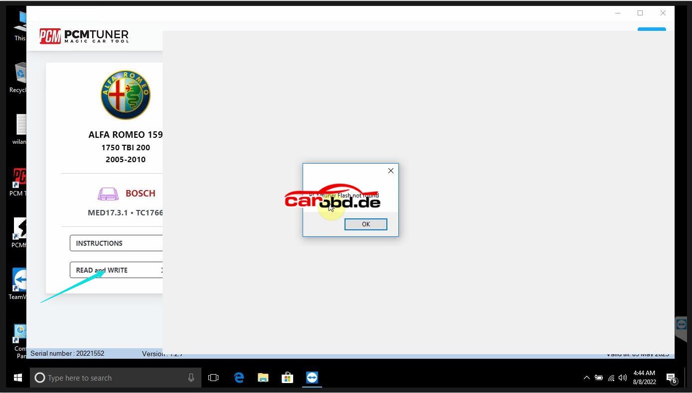
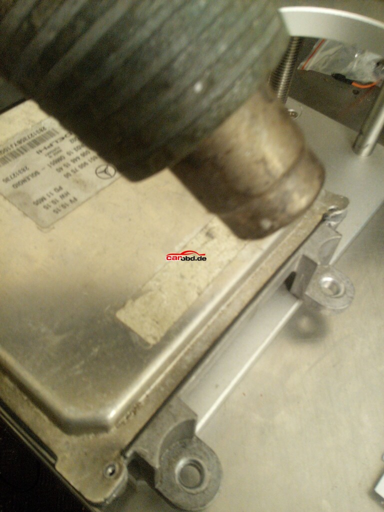
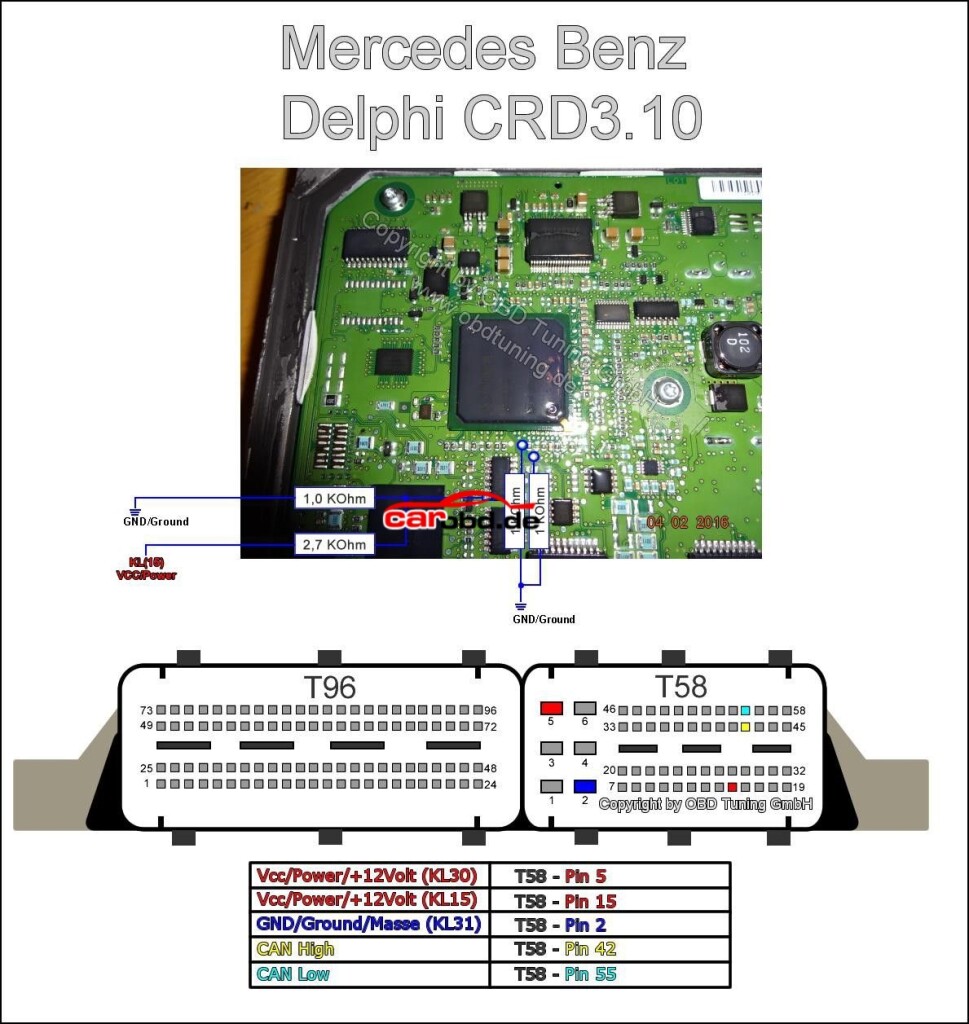
For our example we are going to Read and write both Flash memory and EEPROM from a Delphi CRD3.10 in this case, the ecu is from a 2012 Mercedes C250 blue efficiency model, a car not on our current module list.
With a little research we can find
1. ECM type and specifications
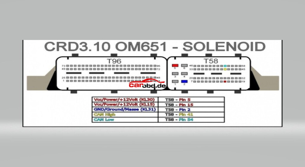
2. ECM pinouts
3. boot loader connections for pcb
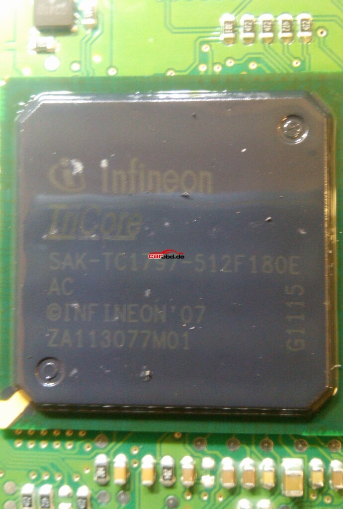
Processor type TC1797
Password: Not implemented
Eeprom external

1
Step 1.
We need to dismantle the ECU in order to access the PCB to enable us to place the ecu in boot mode so that we can read/write.
First we remove the screws from the ecu case.

2
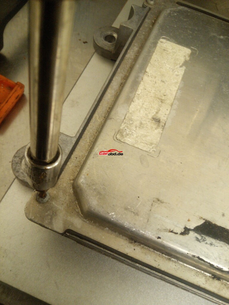
Next, using a heat gun, we gently heat the edges of the ECU lid to help loosen the bonding material, whilst gently prying the lid. Care must be taken not to use excessive heat or force!!

3
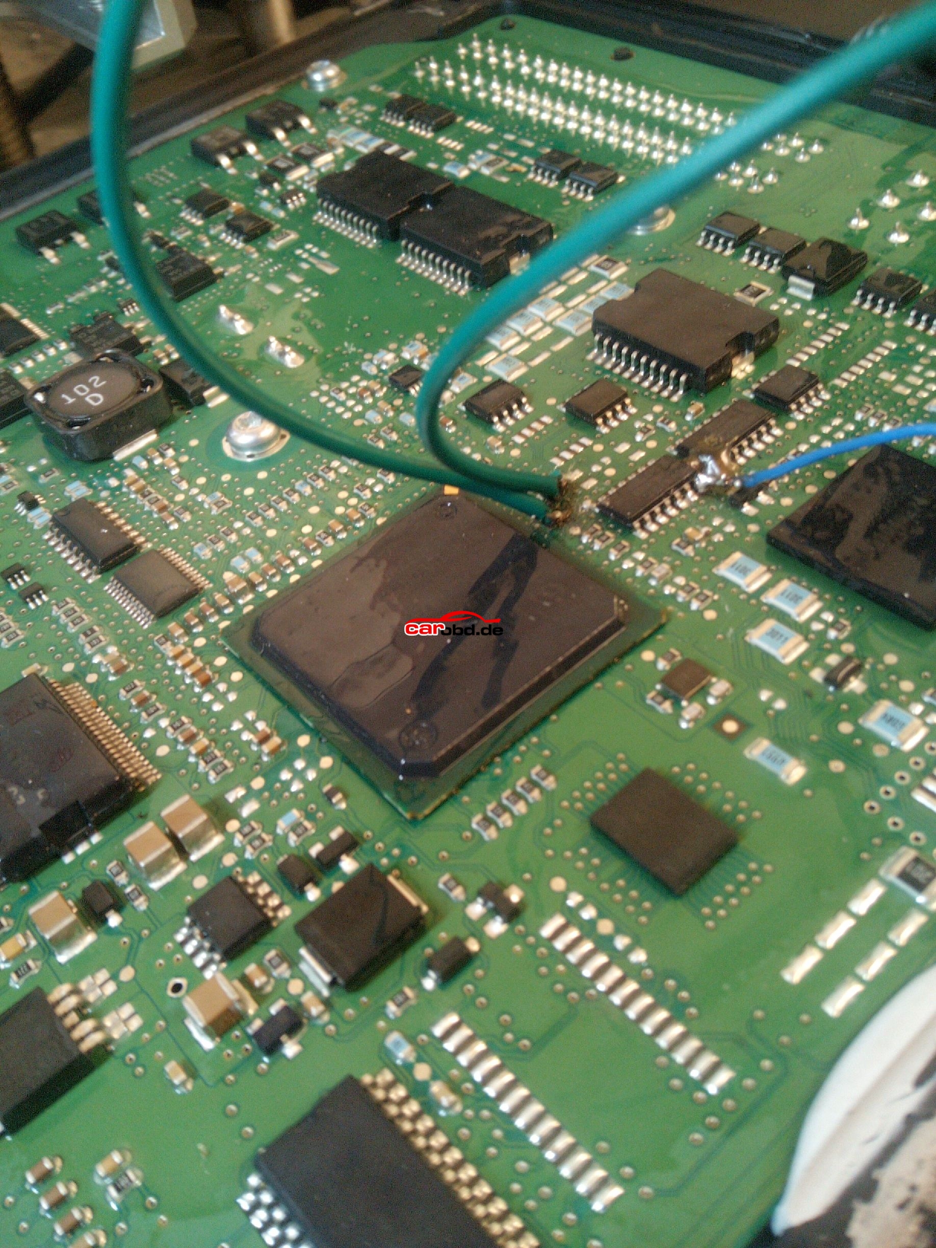
After removing the Lid we now have access to the ECU’s pcb.

4
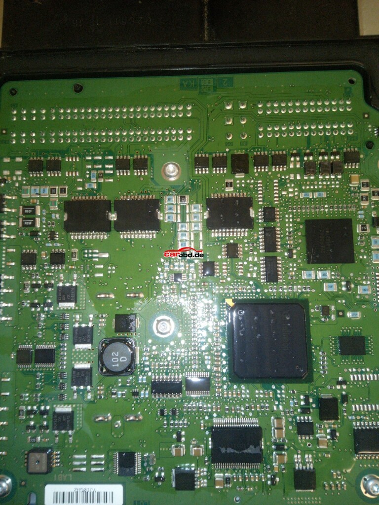
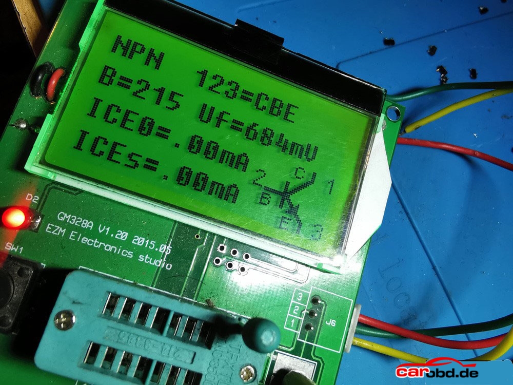
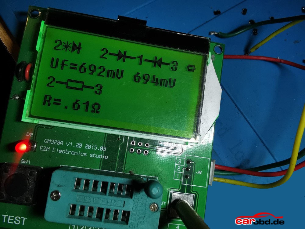
Closer inspection of theprocessor shows it to be a tricore 1797

5
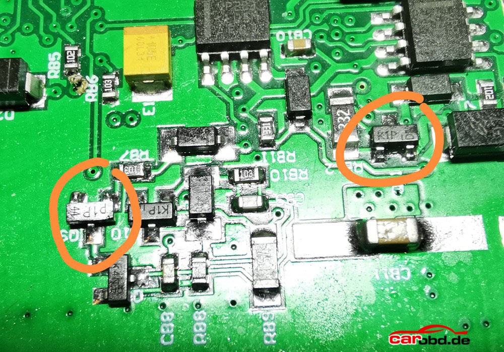
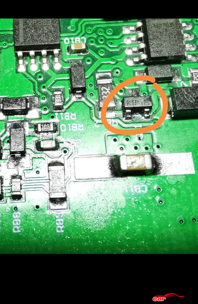
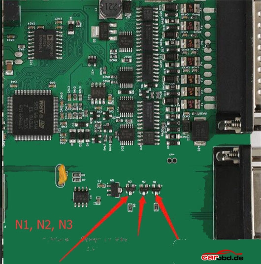
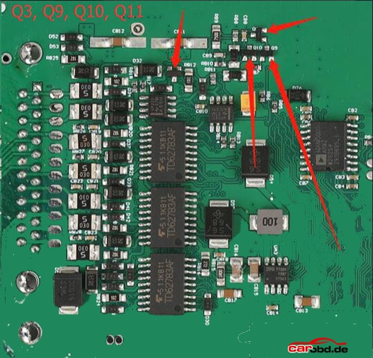
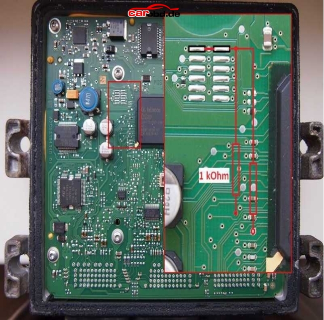
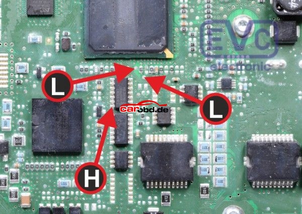
Now we must prepare the PCB for boot mode. Below are just some of the Schematics available via online resources on how to place this ecu into BSL or boot mode. Some will show connections for resistors to be soldered. These type are usually our last resort if we cannot use our boot and cnf cables.

6
Others may show the Labels L and H

7
and others BOOT and CNF1

8
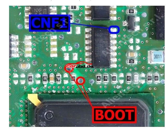
L = Boot H = CNF1 which also relate to the cables on
PCMtuner bench wires with crocodile clips.
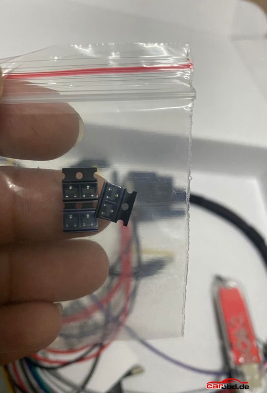
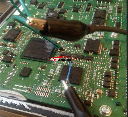
In order to connect to the points shown we can use pen probes (recommended ) or we can solder leads directly to these points that are usually pads, vias or IC pins.

9
With our PCMtuner interface NOT powered, we can connect or bench cable to the ECU

10
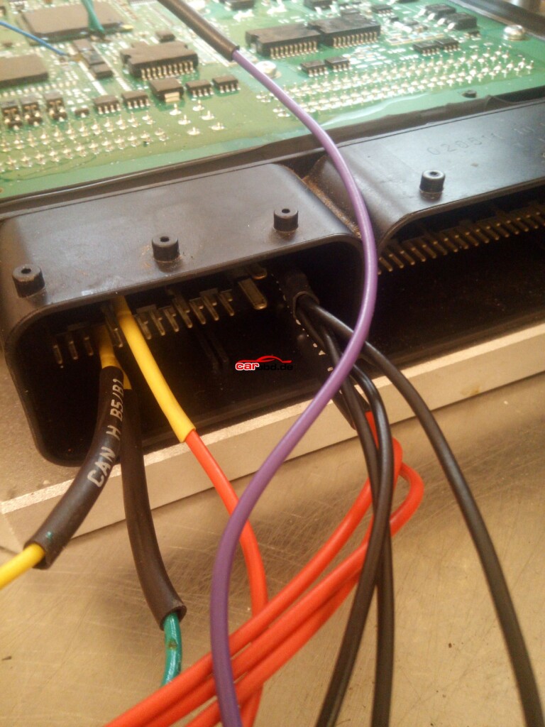
And connect our BOOT and CNF1 to the appropriate leads or Probe pens on the PCB

11
Step 2.
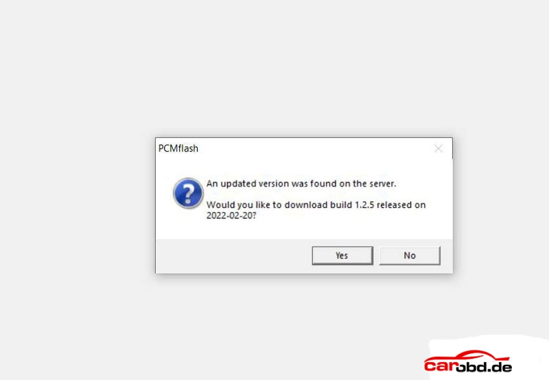
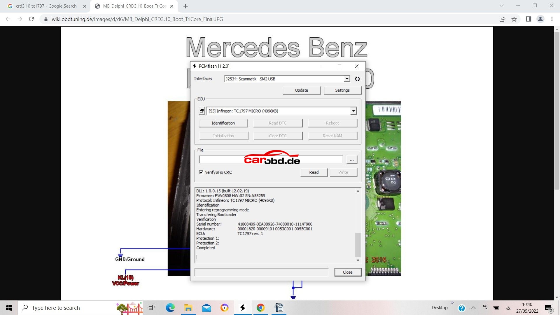
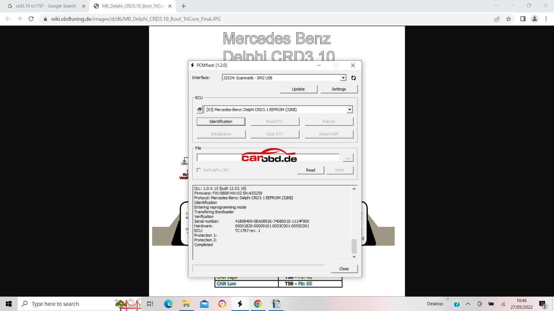
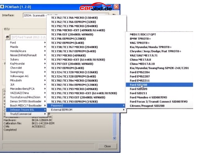
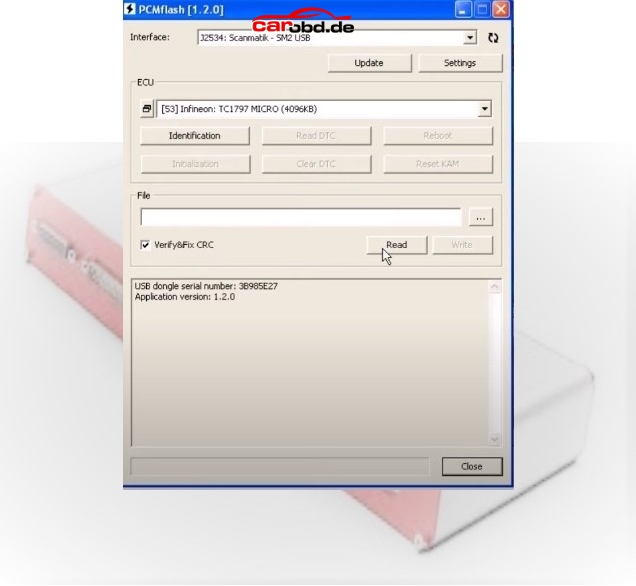
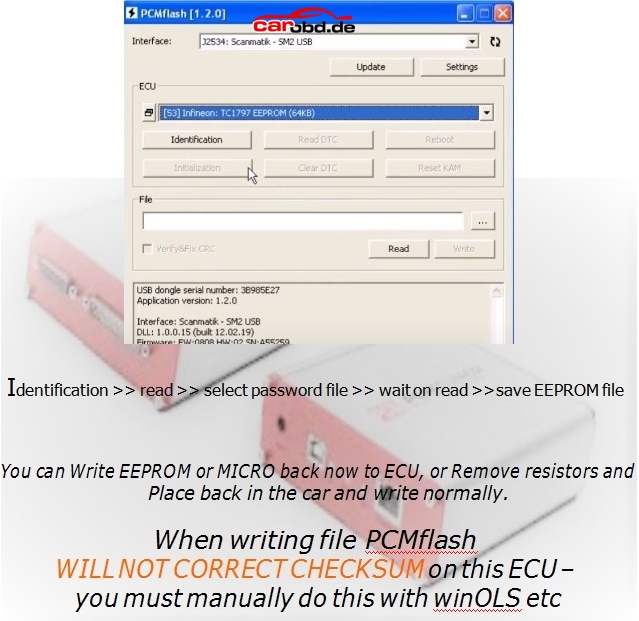
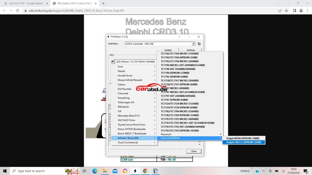
Power on our PCMtuner hardware, open PCMflash, and select module 53 TC1797 Micro (4096kb)
Our Micro is where our flash memory containing maps etc is located.

12
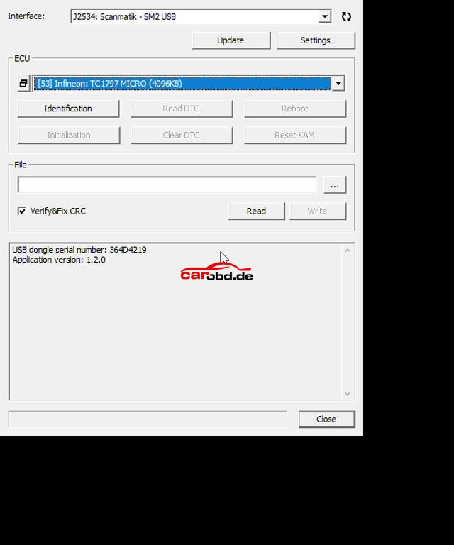
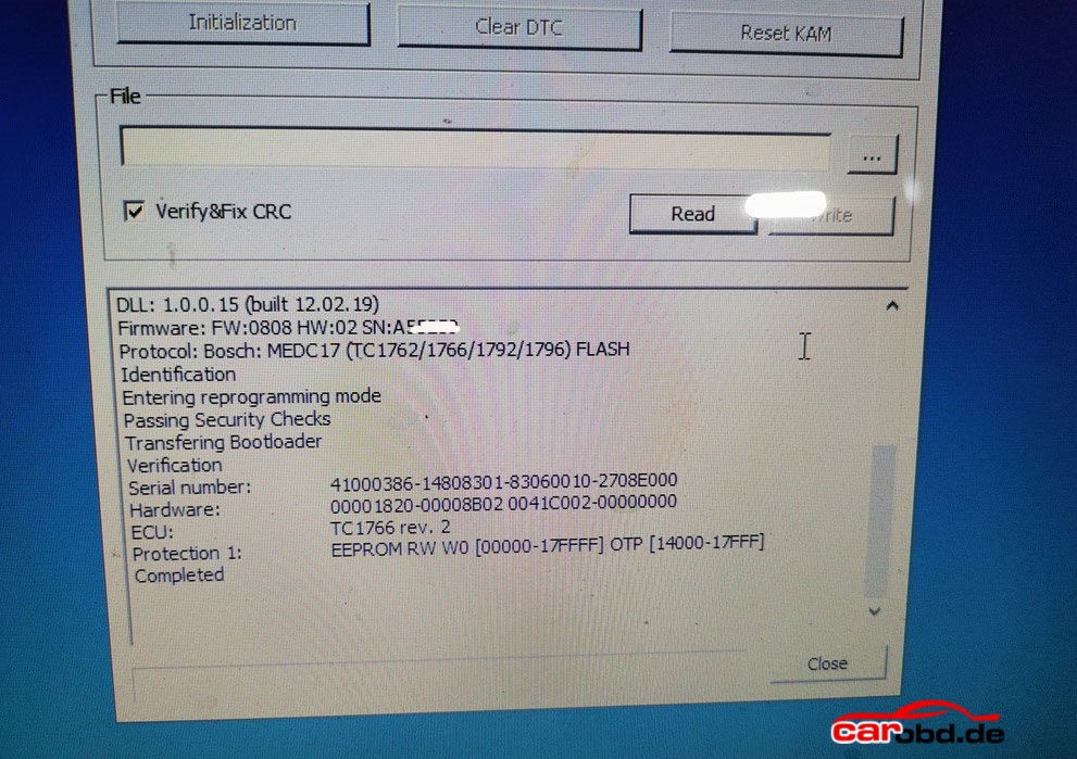
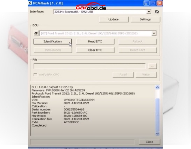
Next we click on Identification to ensure our connections and selection is correct

13
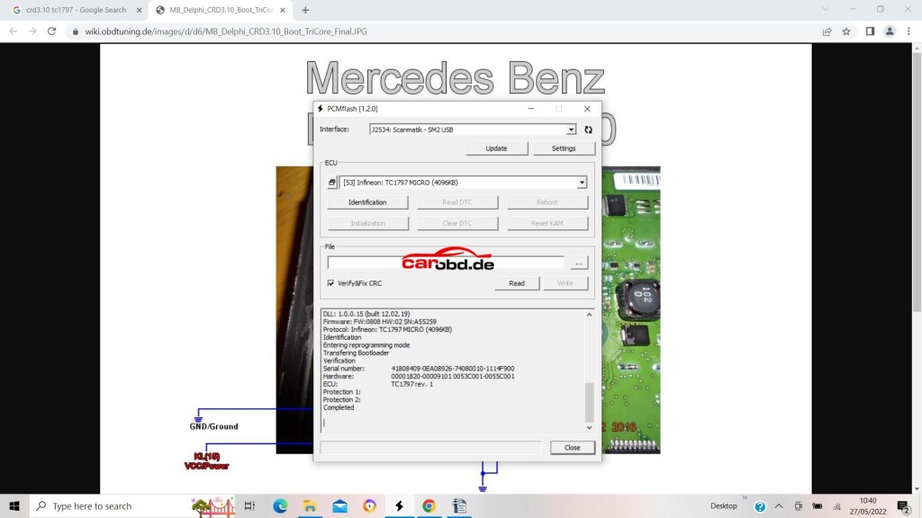
If you cannot ID then please check all connections to PCB, check ECU pinouts, or, in some cases you may have to revert to a diagram that shows
boot and cnf connections as resistors rather than a physical connection to your bench cable.
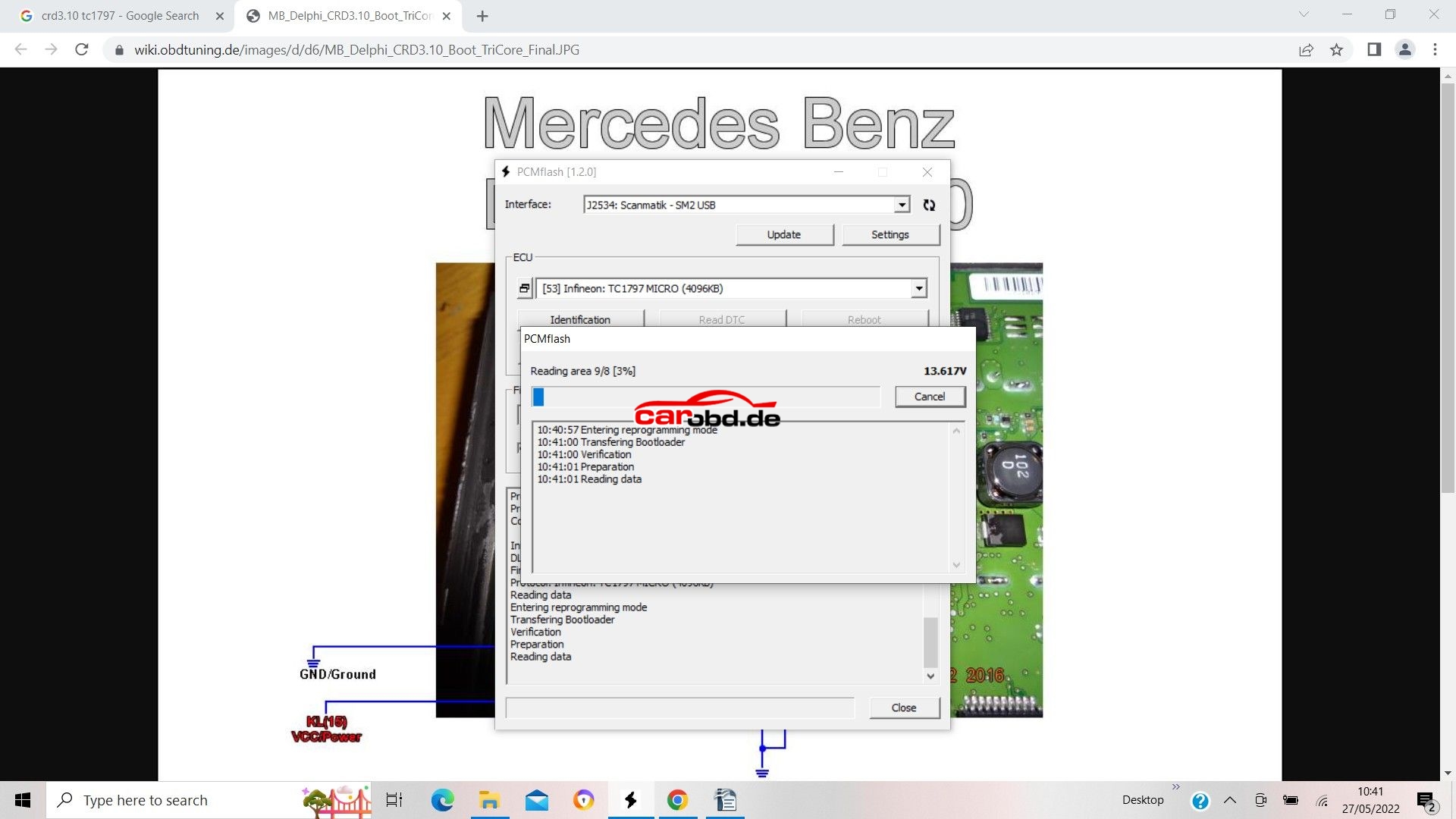
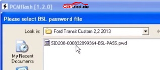
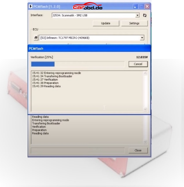
Next we click on Read, We will be asked to select password, in this ECU case we specify that it is not implemented.

14

15
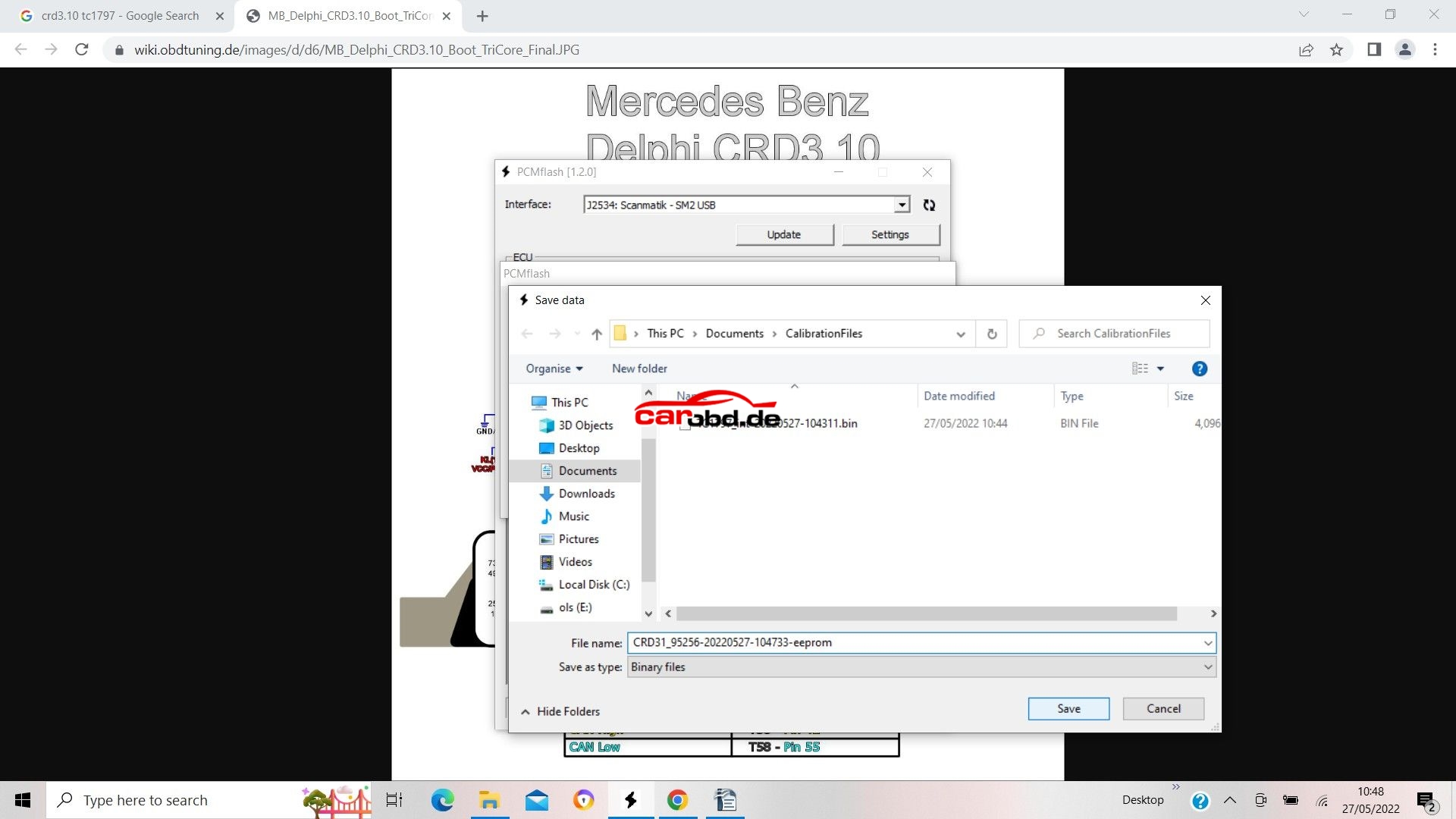
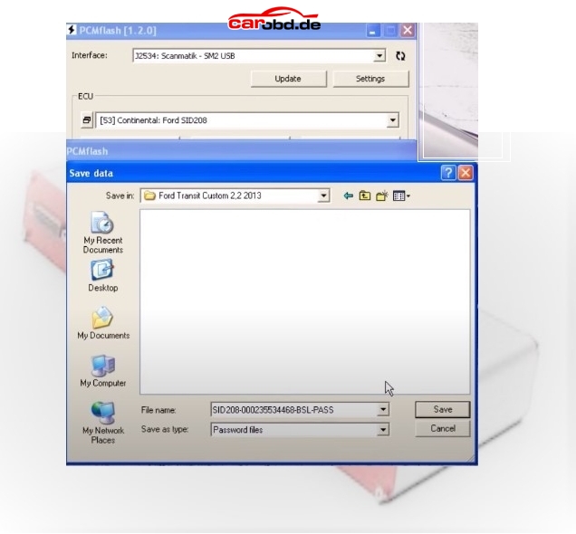
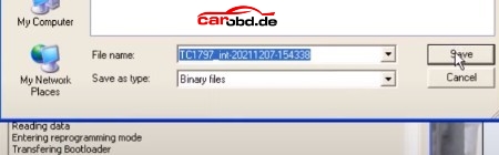
When read is complete we will be asked to save the file
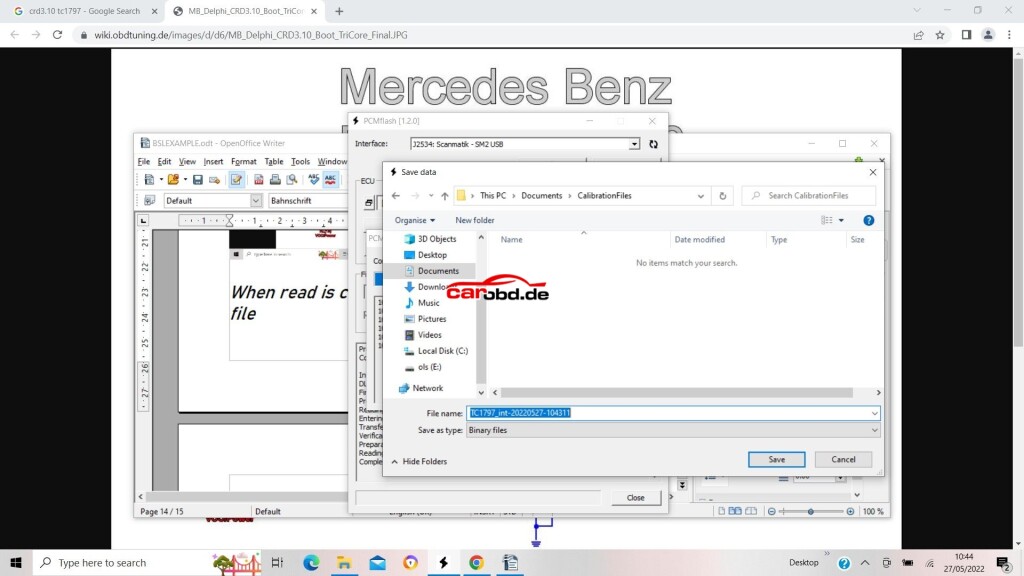
16
click save…
Now we will read our eeprom. In the case of this particular ECU its is an external Ic, so we select the option via MODULE 53>>external eeprom>>Delphi CRD3.1 eeprom

17
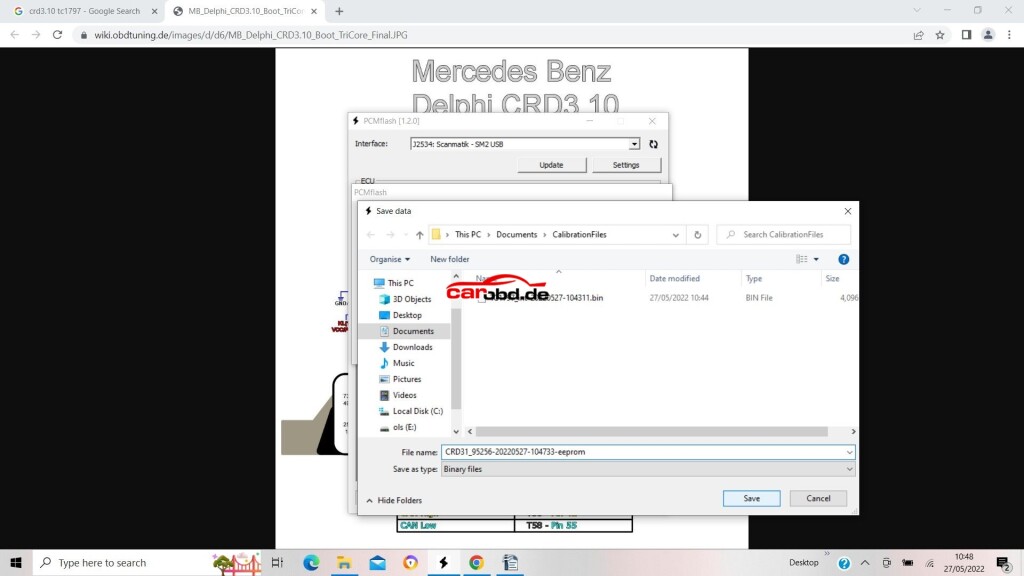
Again, click Identification..then read

18

and again save on the computer when done

19
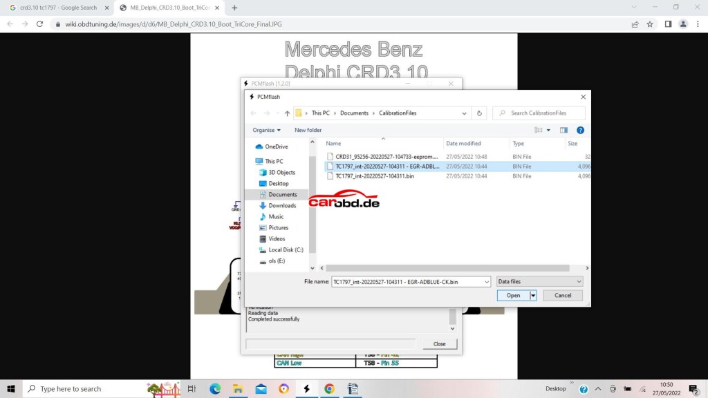
To write a file to flash, we select our micro and click the file selection box

20
we then choose the file we wish to write…..

21
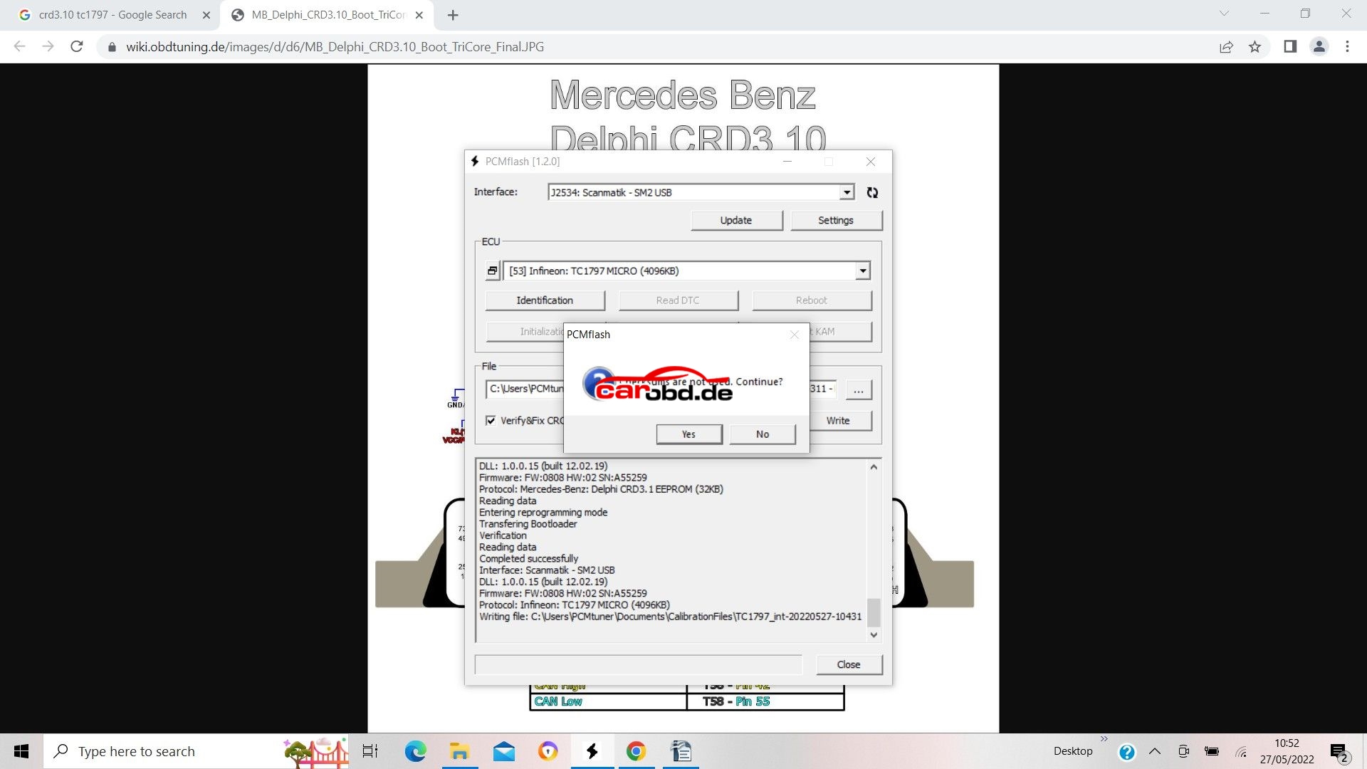
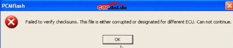
On this Particular ECU we must do our checksum before in our file editor as this automatic checksum function is not implemented


22
So we click yes……
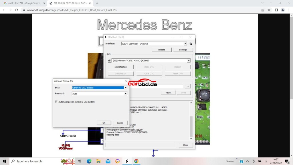
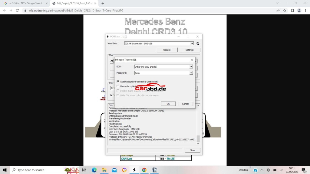
For our ECU we must select ‘other (no crc checks) in the first drop down box.
Password is Auto (as not used on this ecu)’use write optimizations’ is unchecked. This means the full flash file is written. If checked, only changes in the file will be written to Flash –
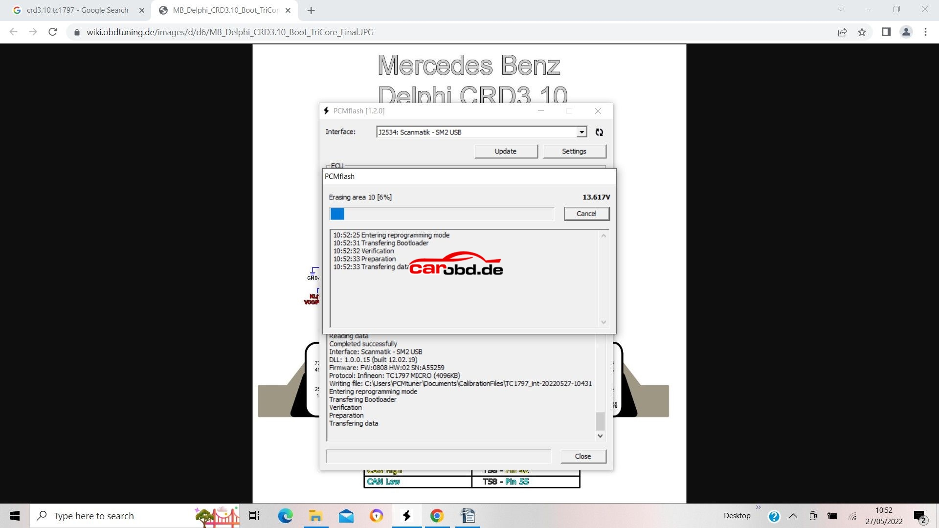
We then click OK

23
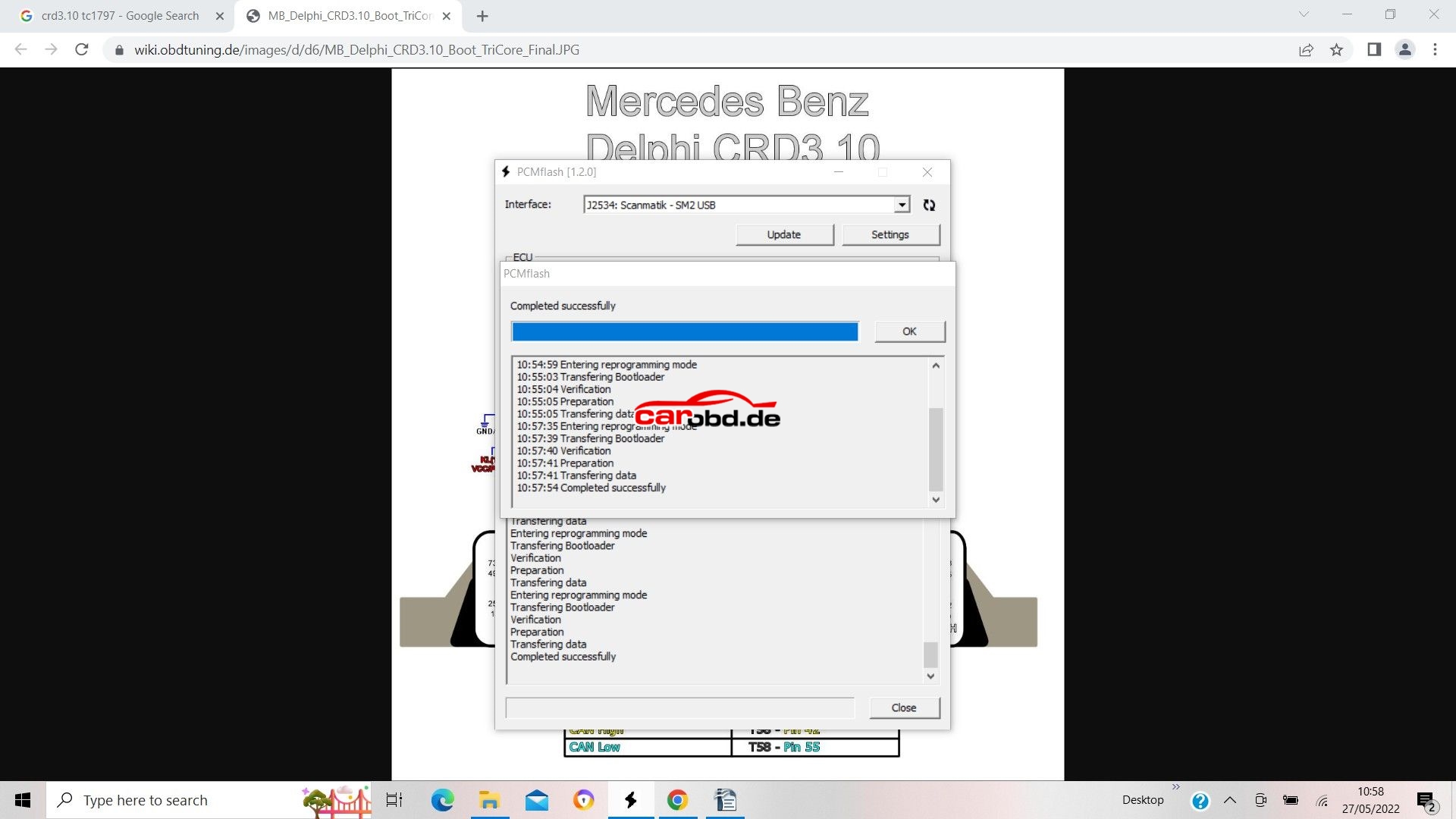
Sit back, have a beer and wait on your latest masterpiece being written to the ECU

24
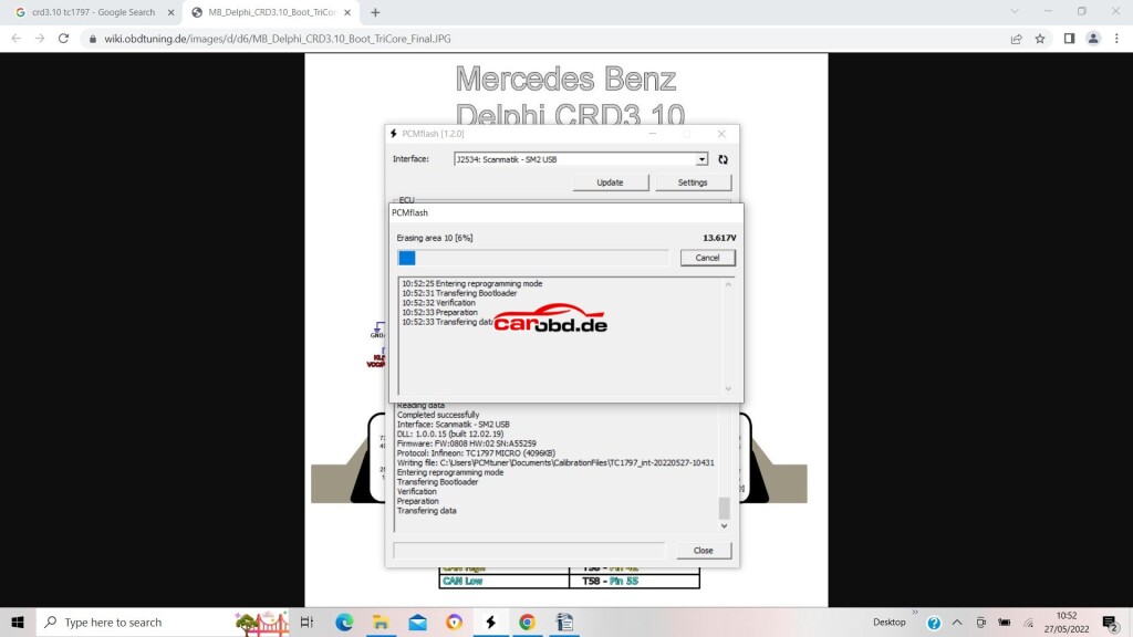
If all goes to plan….Successful write!!!
25

Ford SID208 SID209 BSL INSTRUCTIONS for PCMTuner

Ford SID208 SID209 BSL INSTRUCTIONS for PCMTuner

Just select ECU during operation;

Step 1.
First,with ECU in the car(or on the bench with OBD breakout),we will identify our ECU
To do this, select 07 SID208 and click Identification

step1

Our ECU details can now be seen, If needed we can make a note of these for any future reference.

Step2.

Now we must get the password from the ECU.

To do this we must use the Password option on module 71, and select SID208

step2

Step 3.

Now we click the Read button

step3

The program extracts the password from the ECU

you will now be asked to save it to a file (the serial number of the ECU will be in the file name, it is also indicated on the cover of the ECU itself).
Please remember where you save this file.

step3-2

At same time the program will display the status of the ECU, i.e. whether signature verification is enabled or not.

step3-3

If signature verification is already disabled, then someone has done it before, in this case, just can just write to the ECU as a regular SID208 or SID209.

Step 4.

Open the ECU and, looking at the picture, make the following connection:
Connect 1 kΩ resistors to two via points, connect the end of the resistors to the two upper pads.

step4

Always be careful when you open ecu and when you are soldering not to damage components

Step 5.

In the PCMflash select 53 TC1797 micro and press the Read button

step5

The program will ask you to point to a file with a password, you must change from auto to browse and select the file saved in the first step.

step5-1

The ECU Micro memory will now start to read.

step5-2

Reading time is around 2-3 miwnutes., The Full Memory is Read from the ECU. When Prompted please save the file.

step5-3

Now repeat the above steps for the EEPROM. Select module 53 TC1997 EEPROM

step5-4

step5-5

step5-6

for more informations ,please check following product link

https://www.carobd.de/wholesale/pcmtuner-ecu-programmer.html